UTEC boost control solenoid install question...
 01-21-2008, 03:38 PM
#1
Since the instructions that come with it are useless (they are for installing it on a WRX), and the instructions on TurboXS's website seem to be for a different selenoid, I am having some trouble figuring out the wiring for the BCS.
The instructions on TXS's website show this:
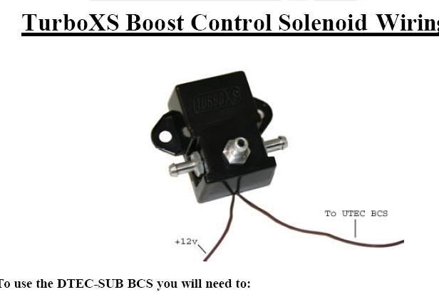
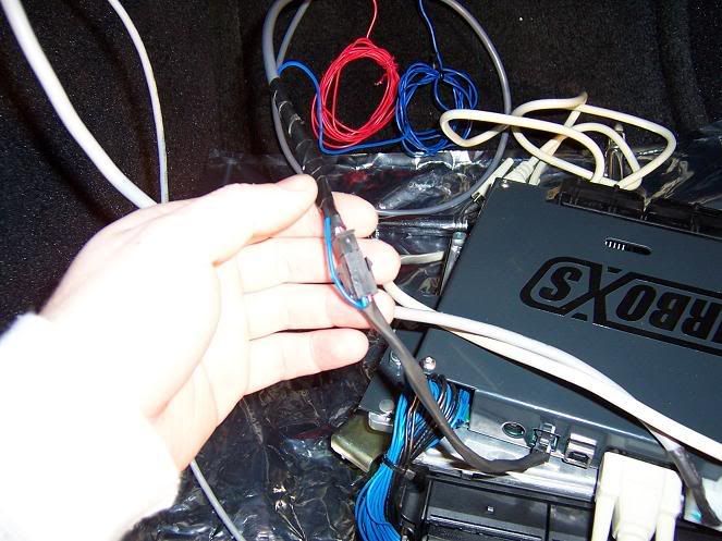
So, two wires on the BCS... one runs to +12v and one to pin 2 on the molex. Simple... But my BCS has three wires... A long red one, a long blue one which is hardwired into the 4 port MAP sensor plug, and a short black one, which I assume is a ground. So I grounded the black one:
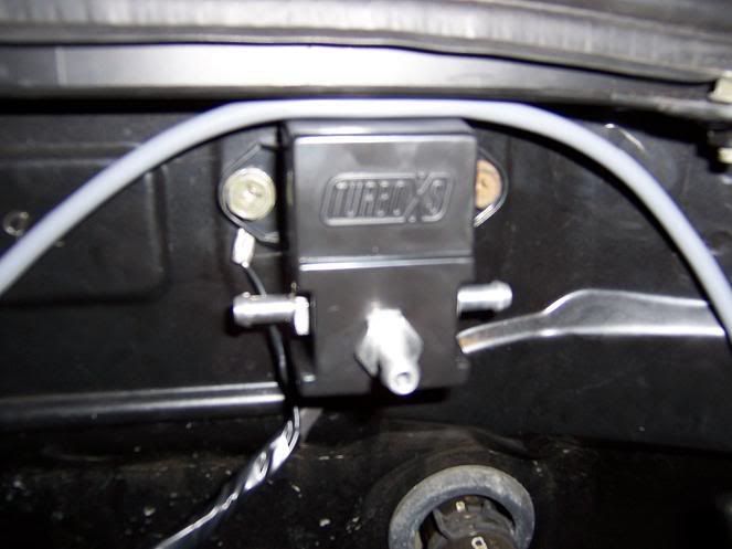
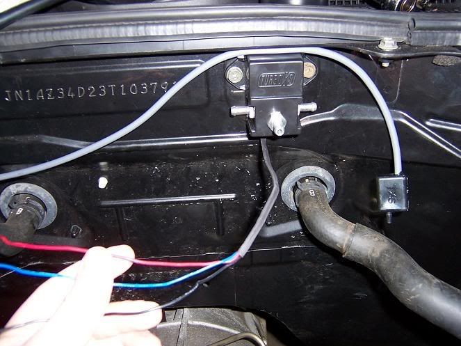
And run the blue one (with the MAP sensor piggyback harness and plug) and the red one thru the firewall and into the pass side footwell where the UTEC is:
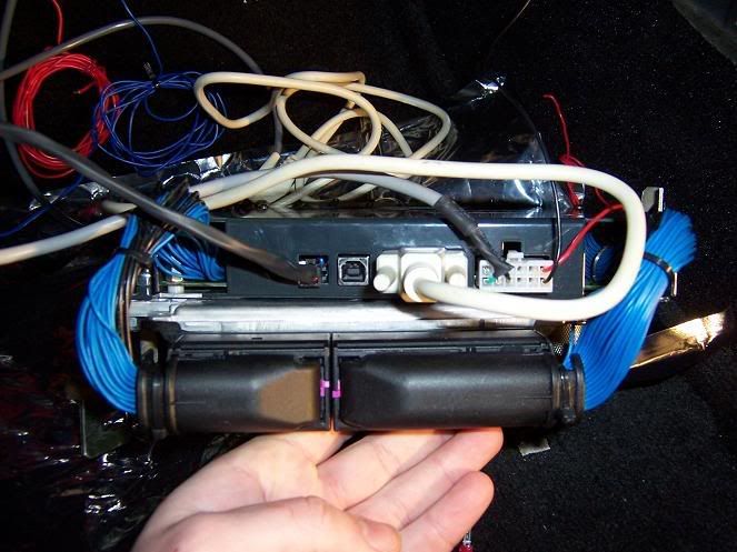
So the blue wire is not in question, since it is already wired into the MAP sensor piggyback harness, which the MAP sensor then plugs into.
But does the red one go to pin 2 on the Molex, or to +12v?
The instructions on TXS's website show this:
So, two wires on the BCS... one runs to +12v and one to pin 2 on the molex. Simple... But my BCS has three wires... A long red one, a long blue one which is hardwired into the 4 port MAP sensor plug, and a short black one, which I assume is a ground. So I grounded the black one:
And run the blue one (with the MAP sensor piggyback harness and plug) and the red one thru the firewall and into the pass side footwell where the UTEC is:
So the blue wire is not in question, since it is already wired into the MAP sensor piggyback harness, which the MAP sensor then plugs into.
But does the red one go to pin 2 on the Molex, or to +12v?
 01-21-2008, 04:12 PM
#2
after reading this thread: https://my350z.com/forum/showthread....ntrol+selenoid
....I am now more confused then ever. The black wire is supposed to go to the Molex #2 pin according to that thread, but if thats the case I dont see why they ship it with only about 6 inches of wire.
Am I supposed to cut the blue wire out of that MAP sensor piggyback harness because its not used on the Z utec? Do both red and blue go to +12v? Argh, something so simple is so confusing because TXS's instructions are **** poor.
Someone save me before I strangle something fluffy.
01-21-2008, 04:34 PM
#3

don't ground any of the wires to the chassis!
Unfortunately, I don't remember which wire does get used. But, you will connect one of the wires to 12V. the other wire gets connected to the utec trigger (it's a negative trigger.)
I'm gonna dig through my "archives" and see if I can find which wires to use.............
Unfortunately, I don't remember which wire does get used.
But, you will connect one of the wires to 12V. the other wire gets connected to the utec trigger (it's a negative trigger.)I'm gonna dig through my "archives" and see if I can find which wires to use.............
01-21-2008, 04:47 PM
#4
I just took my car apart to look at my setup.........
my BCS has 2 brown wires.
My assumption would be to use the red and blue wires. It doesn't matter which wire you use for +12V and which one you connect to the UTEC negative trigger. The solenoid works either way. Now, the small wire.....I don't knowwhat that's for, but I would just tape it off for now. Call TXS in the morning if you ar really concered.
01-21-2008, 05:19 PM
#6
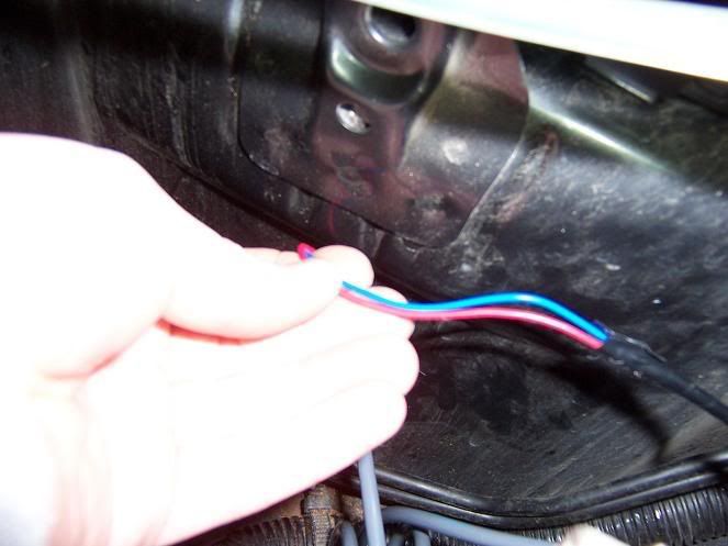
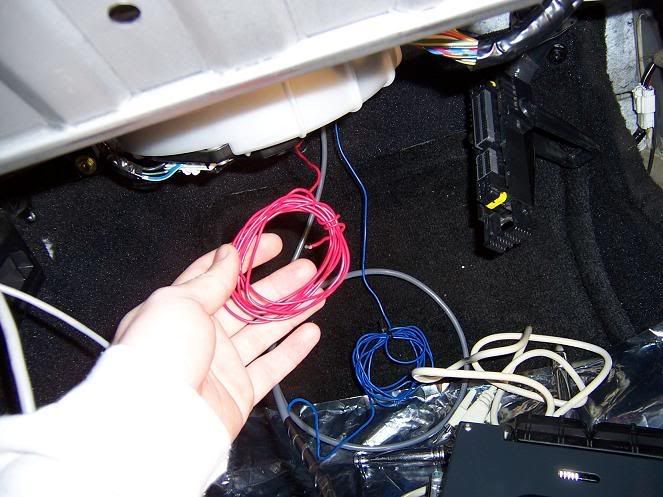
Okay, so I went back to sqare one and undid the grounded black wire and disconnected the blue wire. That leaves me here:
Red, blue, and black wires coming out of BCS
Both the red and black wires terminate in a cut end. The blue wire, however, ends as part of this harness:
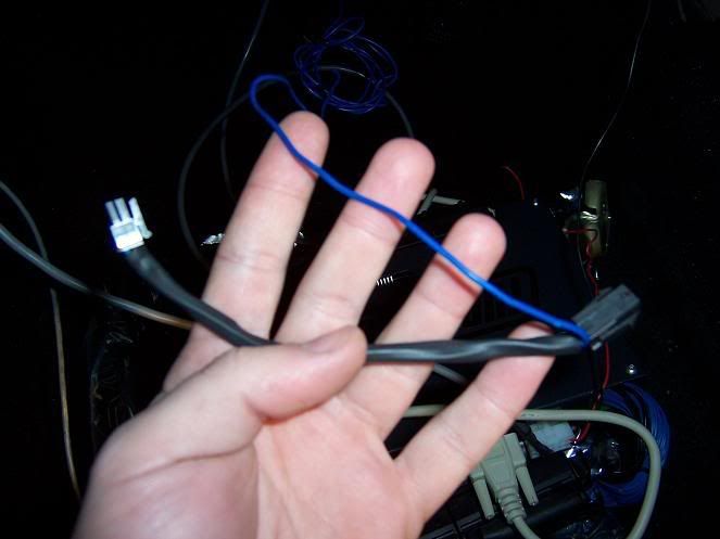
I figured that this harness plugged in inline between the UTEC and the MAP sensor. Does this not apply on the Z? If not I guess I just cut the blue wire out of it. But I still dont know which wire goes where.
I am going to call TXS tomorrow, hopefully their tech support is a little better then their "instructions"... lol
Red, blue, and black wires coming out of BCS
Both the red and black wires terminate in a cut end. The blue wire, however, ends as part of this harness:
I figured that this harness plugged in inline between the UTEC and the MAP sensor. Does this not apply on the Z? If not I guess I just cut the blue wire out of it. But I still dont know which wire goes where.
I am going to call TXS tomorrow, hopefully their tech support is a little better then their "instructions"... lol
01-21-2008, 06:02 PM
#7
Imakecopies

iTrader: (13)
Join Date: May 2004
Location: Charleston, SC
Posts: 2,330
Likes: 0
Received 0 Likes
on
0 Posts
Cut that plug off, its for the wrx or something.
**From the most respected source on these boards:
It's easy. The blue and red wires get tired together, and routed to switched 12V power.
Black wire goes to pin #2
**From the most respected source on these boards:
It's easy. The blue and red wires get tired together, and routed to switched 12V power.
Black wire goes to pin #2
Last edited by Ahsmo; 01-21-2008 at 06:05 PM.
Trending Topics
 01-21-2008, 06:17 PM
#9
Originally Posted by Ahsmo
Cut that plug off, its for the wrx or something.
**From the most respected source on these boards:
It's easy. The blue and red wires get tired together, and routed to switched 12V power.
Black wire goes to pin #2
**From the most respected source on these boards:
It's easy. The blue and red wires get tired together, and routed to switched 12V power.
Black wire goes to pin #2
 01-21-2008, 06:22 PM
#10
Registered User
iTrader: (3)

Join Date: Dec 2003
Location: Wilmington De
Posts: 961
Likes: 0
Received 0 Likes
on
0 Posts
good luck with that. i got frustrated trying to get the boost control solenoid to work with the utec. went with the blitz sbc. i just have to press two buttons(one for the blitz, one for the map selector) instead of one now, but its less of a hassle than trying to get that solenoid to work. there was a thread mrc started awhile go about getting the boost control function to work on the utec. check it out.
01-21-2008, 06:26 PM
#11
Imakecopies
iTrader: (13)
Join Date: May 2004
Location: Charleston, SC
Posts: 2,330
Likes: 0
Received 0 Likes
on
0 Posts
Originally Posted by SpoilsofWar
Cool, that was the kind of straight to the point answer I was looking for
As that thread shows...it took me a while to figure it out. I finally got a hold of one of the sponsers who told me the magic secret.
01-21-2008, 07:09 PM
#13
Yeah, I got a molex terminal with mine as well, with a length of black wire attached to it. I guess I should have taken this as a clue that you are supposed to crimp it to the black wire that comes out of the BCS, and that wire is the one used to connect to the BCS output from the UTEC.
I never would have guessed that both the red and blue wires were supposed to be twisted together and attached to +12v, though.
I never would have guessed that both the red and blue wires were supposed to be twisted together and attached to +12v, though.
01-21-2008, 07:13 PM
#14
Originally Posted by Bullitproof
good luck with that. i got frustrated trying to get the boost control solenoid to work with the utec. went with the blitz sbc. i just have to press two buttons(one for the blitz, one for the map selector) instead of one now, but its less of a hassle than trying to get that solenoid to work. there was a thread mrc started awhile go about getting the boost control function to work on the utec. check it out.
Anyway, I was under the impression that most of the issues with the UTEC controlling boost were due to older versions of the UTEC software and that updates have fixed most of them. I realize the BCS is not the most elegant solution and that a seperate EBC would probably be superior - but there seems to be a good number of people using it without problems.
01-21-2008, 07:17 PM
#15
I wouldn't expose the BCS to the heat in the engine compartment. The solenoids usually have a temp limitation of 110 degrees farenheit. Mine is in the battery compartment. Electrical resistance varies with temperatures.
JET
JET
Last edited by JETPILOT; 01-21-2008 at 07:53 PM.
01-22-2008, 03:07 AM
#17
Imakecopies
iTrader: (13)
Join Date: May 2004
Location: Charleston, SC
Posts: 2,330
Likes: 0
Received 0 Likes
on
0 Posts
Originally Posted by JETPILOT
I wouldn't expose the BCS to the heat in the engine compartment. The solenoids usually have a temp limitation of 110 degrees farenheit. Mine is in the battery compartment. Electrical resistance varies with temperatures.
JET
JET
01-22-2008, 01:27 PM
#18
Banned
iTrader: (1)

Join Date: Feb 2004
Location: Dayton, OH
Posts: 2,128
Likes: 0
Received 0 Likes
on
0 Posts
From what I've read and experianced as long as you are running low boost you should be OK. If you try to run higher boost expect problems. The 'gain' control of the UTEC doesn't appear to do anything at all. Not having control of the gain makes it near impossible to prevent overboosting.
I'm amazed that TurboXS hasn't addressed this issue at all over the past year.
I'm amazed that TurboXS hasn't addressed this issue at all over the past year.