NE1 removed PCV on passenger side valve cover?
 12-19-2008, 12:18 PM
#121
Registered User
iTrader: (1)

Join Date: Oct 2004
Location: MARS
Posts: 111
Likes: 0
Received 0 Likes
on
0 Posts
Gee that really helps a lot fellas. I read the link and this entire post. I still have not seen/read a solution. Apparently I'm not the only one either. I cant understand why you would start a thread on a possible fix for the G/Z only to mock the people reading it. Thanks again.
 12-22-2008, 08:00 AM
#122
Registered User
iTrader: (25)
Join Date: Jan 2006
Location: Phoenix
Posts: 784
Likes: 0
Received 0 Likes
on
0 Posts
I have to agree. The solution on that other site will not introduce any vacuum to the system on the pass side to pull out blow by. The good news it that it will work under boost unlike the PCV but at low rpm the oem setup works better.
There have been many ideas in this thread but none seem to be the "ideal" solution.
There have been many ideas in this thread but none seem to be the "ideal" solution.
12-22-2008, 09:43 AM
#123
I have to agree. The solution on that other site will not introduce any vacuum to the system on the pass side to pull out blow by. The good news it that it will work under boost unlike the PCV but at low rpm the oem setup works better.
There have been many ideas in this thread but none seem to be the "ideal" solution.
There have been many ideas in this thread but none seem to be the "ideal" solution.
12-22-2008, 07:58 PM
#124
Look, if you're starting out today, the ideal, low cost solution is:
1. opening up the driver's side port, which is only a small hole, despite the 5/8" hose connected to it (too much trouble for me to mess w/ valve cover removal and replacement)
2. drilling out the PCV (easy, now that I've been schooled)
3. using a catch can to intercept oil vapors (easy)
4. using open air breathers where you want to draw air in and also under high blow by conditions provide a safety release path.
5. slightly more complicated - use vacuum sources you know to exist at idle and boost (plenum and turbo intake) OR exhaust siphon - and use those to create suction out of the catch can(s).
- this problem seems beat to death to me at this point. as jet pointed out, it seems to work well enough to not spend time investigating further...
12-23-2008, 01:16 AM
#125
Registered User

Join Date: Jun 2007
Location: F/I
Posts: 239
Likes: 0
Received 0 Likes
on
0 Posts
Look, if you're starting out today, the ideal, low cost solution is:
1. opening up the driver's side port, which is only a small hole, despite the 5/8" hose connected to it (too much trouble for me to mess w/ valve cover removal and replacement)
2. drilling out the PCV (easy, now that I've been schooled)
3. using a catch can to intercept oil vapors (easy)
4. using open air breathers where you want to draw air in and also under high blow by conditions provide a safety release path.
5. slightly more complicated - use vacuum sources you know to exist at idle and boost (plenum and turbo intake) OR exhaust siphon - and use those to create suction out of the catch can(s).
- this problem seems beat to death to me at this point. as jet pointed out, it seems to work well enough to not spend time investigating further...
1. opening up the driver's side port, which is only a small hole, despite the 5/8" hose connected to it (too much trouble for me to mess w/ valve cover removal and replacement)
2. drilling out the PCV (easy, now that I've been schooled)
3. using a catch can to intercept oil vapors (easy)
4. using open air breathers where you want to draw air in and also under high blow by conditions provide a safety release path.
5. slightly more complicated - use vacuum sources you know to exist at idle and boost (plenum and turbo intake) OR exhaust siphon - and use those to create suction out of the catch can(s).
- this problem seems beat to death to me at this point. as jet pointed out, it seems to work well enough to not spend time investigating further...

But is the easy solution to drill out PCV and driver's side port, vent both sides to atmosphere (through a catch can on each side) and no PCV or check valve?
01-05-2009, 05:31 PM
#126

Hmmmm im still debating what would be the best thing to do.... maybe ill just leave it the way it is for now... considering i only am boosting at 9psi, i think the driver side vent will be more than adequate to dissipate the pressure. Also the pcv valve only lets a tiny amount of boost back into the crank case..
I am leaning toward JETPILOTs idea of drilling the pcv and putting a breather there and just leaving the driver side, because I would prefer not to have the crankcase gasses recirc to my plenum, but apparently in his other post he said it doesnt do anything? He didnt elaborate
I am leaning toward JETPILOTs idea of drilling the pcv and putting a breather there and just leaving the driver side, because I would prefer not to have the crankcase gasses recirc to my plenum, but apparently in his other post he said it doesnt do anything? He didnt elaborate
Last edited by jining; 01-06-2009 at 11:39 AM.
01-17-2009, 08:41 AM
#127
Registered User

OK guys 1st of all am not boosted but i`ve tried two ways before !!
1- Put a Catch Can In-line between the PCV Valve and the Plenum, and it did really work the Catch can collected lots of oil withing 3-4 weeks it went to half (am using the big GReddy Catch Can 1 Liter).
2 - I saw ARC catch can and saw rcdash idea with the Check valves but decided to do it later on when i`m Boosted, so what i did now is Capping the Plenum off, and i`ve Drilled my Catch Can for an additional Line, i`ve installed the Catch Can in-line between the Intake and the Driver side valve cover vent, and connected the PCV Valve to the additional line on the Catch Can.
Regarding the second way, rcdash told me before that this way will not work like stock because there`s not enough vacuum, the intake will not do as strong as the plenum at idle and it might work well just under WOT because the intake will such both sides, but here comes the most important part about this way !!!
i`ve learned this after reading this document its well written 1000 times better than the FSM.
During Idle the Vacuum at the manifold will be at its greatest so the PCV Valve will open up a little but during light load it will open half its way and during WOT there will be almost no vacuum at the manifold so the PCV Valve will be fully open.
so by connecting the PCV Valve directly to the Intake at WOT the PCV Valve will open up very very little like idle time on the manifold and will allow only a SMALL amount of the oil/vapor to escape and this is what u really don`t want especially at WOT, thats why my catch can reached only 3/4 with this setup from march 2008 !!!!
PCV Valve will always be hooked up to the Plenum in all cases NOT Intake !!! Except if u drill it its not a valve anymore
so what am gonna do next is :
Drill the PCV Valve just like what you guys did, and try 2 ways:
Flow Direction -------->
PCV----------->Catch Can------->Right Pre-Turbo Intake
Driver Side----->Catch Can------->Left Pre-Turbo Intake
and if it didn`t work and i know u guys will tell me that i`m not doing a ventilation because no fresh air is entering here is the other way:
Its basically the same but i`ll disconnect the hose connecting each valve cover together and put a Breather Filter on each side so that both Turbos draw in fresh air through the K&N Breathers and also all of this is Metered air it will not affect people running MAF also it does not matter ur at boost or off boost
  not to forget its a failsafe as rcdash mentioned if anything happen the oil will escape thorough the Breather Filter.
but what i really want to know here is the difference between the two ways lol ? and why we really wanna draw in freash air to the crankcase :1
1- Put a Catch Can In-line between the PCV Valve and the Plenum, and it did really work the Catch can collected lots of oil withing 3-4 weeks it went to half (am using the big GReddy Catch Can 1 Liter).
2 - I saw ARC catch can and saw rcdash idea with the Check valves but decided to do it later on when i`m Boosted, so what i did now is Capping the Plenum off, and i`ve Drilled my Catch Can for an additional Line, i`ve installed the Catch Can in-line between the Intake and the Driver side valve cover vent, and connected the PCV Valve to the additional line on the Catch Can.
Regarding the second way, rcdash told me before that this way will not work like stock because there`s not enough vacuum, the intake will not do as strong as the plenum at idle and it might work well just under WOT because the intake will such both sides, but here comes the most important part about this way !!!
i`ve learned this after reading this document its well written 1000 times better than the FSM.
During Idle the Vacuum at the manifold will be at its greatest so the PCV Valve will open up a little but during light load it will open half its way and during WOT there will be almost no vacuum at the manifold so the PCV Valve will be fully open.
so by connecting the PCV Valve directly to the Intake at WOT the PCV Valve will open up very very little like idle time on the manifold and will allow only a SMALL amount of the oil/vapor to escape and this is what u really don`t want especially at WOT, thats why my catch can reached only 3/4 with this setup from march 2008 !!!!
PCV Valve will always be hooked up to the Plenum in all cases NOT Intake !!! Except if u drill it its not a valve anymore
so what am gonna do next is :
Drill the PCV Valve just like what you guys did, and try 2 ways:
Flow Direction -------->
PCV----------->Catch Can------->Right Pre-Turbo Intake
Driver Side----->Catch Can------->Left Pre-Turbo Intake
and if it didn`t work and i know u guys will tell me that i`m not doing a ventilation because no fresh air is entering here is the other way:
Its basically the same but i`ll disconnect the hose connecting each valve cover together and put a Breather Filter on each side so that both Turbos draw in fresh air through the K&N Breathers and also all of this is Metered air it will not affect people running MAF
also it does not matter ur at boost or off boost not to forget its a failsafe as rcdash mentioned if anything happen the oil will escape thorough the Breather Filter.but what i really want to know here is the difference between the two ways lol ? and why we really wanna draw in freash air to the crankcase :1
 01-17-2009, 04:31 PM
#130
Netshark, I think your new set up should work. It will draw out crankcase vapor at WOT, but will do nothing at idle, which maybe, is ok. The reason you want ventilation is to capture blow by gases that include elements like FUEL vapors so they do not contaminate the oil. This is the first statement in your linked document. My understanding is that positive crankcase ventilation allows air and fuel vapors to preferentially escape versus the heavier oil vapor. With no ventilation, you will evacuate a homogenous mixture of air, oil and fuel vapor. Your catch cans will fill up quicker. I don't know that that is bad though. Might be just fine but I prefer to maintain the ventilation and have a route for fresh air entry into the crankcase.
EDIT: Also Netshark, please note, that I use check valves NOT PCV valves for my evacuation set up. PCV valves have a very specific use because of the flow characteristics that you noted above.
EDIT: Also Netshark, please note, that I use check valves NOT PCV valves for my evacuation set up. PCV valves have a very specific use because of the flow characteristics that you noted above.
Last edited by rcdash; 01-17-2009 at 04:36 PM.
01-18-2009, 08:29 AM
#131
Registered User
1st i wanted to try your trick its impressive !! its very very close to stock setup of course with the PCV Valve drilled and the use of check valves instead as you noted, but it will affect MAF people :/ because it will suck more air at idle which is GOOD to quickly get rid of the vapors and in the same time not good for the MAF because the engine will think its a vacuum leak i know almost all the guys here are with FCon/Haltech/other Standalone EMS so they don`t bother about the MAF anymore  believe me Mr Raj 1st thing i`ll do when i run Standalone is ur setup i like it alot, but now i`ll stick with this Idea because it will not mess with the stupid MAF
and here is my Next Plan i`ll use 2 of this check valve
http://www.mcmaster.com/
7775K63 for 3/8 valve
* Maximum Pressure: Buna-N: 1000 psi @ 250� F; Viton: 1000 psi @ 400� F
* Cracking Pressure: 0.3 psi
* Temperature Range: Buna-N: -40� to +250� F; Viton: -20� to +400� F
Engineered for an extra-low cracking pressure of just 0.3 psi. Valves have a brass piston, 300 series stainless steel spring, and your choice of Buna-N or Viton seats.
Connections: NPTF (Dryseal).
of course the Viton is better and link the male valves on this T Block Adapter from Mr Gasket
http://store.summitracing.com/partde...5&autoview=sku
so i`ll install the valves on the faced sides of the adapter with the flow/arrow pointing away from the adapter and use NPT Female adapter to 3/8 hose barbs on the valves, the barb in the middle of the T Block Adapter will be going to the Catch Can its ur setup Raj but with lmetal valves with good specs on them not to bash the valves u have at all but i guess these will have less maintenance/more life than the plastics but it costs 100 times loool
if the valves is big u can get the 1/4 valves PN: 7775K62 and get a T with 1/4 Female NPT and get the NPT to barb fittings.
of course with the PCV Valve drilled and the use of check valves instead as you noted, but it will affect MAF people :/ because it will suck more air at idle which is GOOD to quickly get rid of the vapors and in the same time not good for the MAF because the engine will think its a vacuum leak i know almost all the guys here are with FCon/Haltech/other Standalone EMS so they don`t bother about the MAF anymore believe me Mr Raj 1st thing i`ll do when i run Standalone is ur setup i like it alot, but now i`ll stick with this Idea because it will not mess with the stupid MAF and here is my Next Plan i`ll use 2 of this check valve
http://www.mcmaster.com/
7775K63 for 3/8 valve
* Maximum Pressure: Buna-N: 1000 psi @ 250� F; Viton: 1000 psi @ 400� F
* Cracking Pressure: 0.3 psi
* Temperature Range: Buna-N: -40� to +250� F; Viton: -20� to +400� F
Engineered for an extra-low cracking pressure of just 0.3 psi. Valves have a brass piston, 300 series stainless steel spring, and your choice of Buna-N or Viton seats.
Connections: NPTF (Dryseal).
of course the Viton is better and link the male valves on this T Block Adapter from Mr Gasket
http://store.summitracing.com/partde...5&autoview=sku
so i`ll install the valves on the faced sides of the adapter with the flow/arrow pointing away from the adapter and use NPT Female adapter to 3/8 hose barbs on the valves, the barb in the middle of the T Block Adapter will be going to the Catch Can its ur setup Raj but with lmetal valves with good specs on them not to bash the valves u have at all but i guess these will have less maintenance/more life than the plastics but it costs 100 times loool
if the valves is big u can get the 1/4 valves PN: 7775K62 and get a T with 1/4 Female NPT and get the NPT to barb fittings.
 01-18-2009, 11:39 AM
#134
Registered User
Sorry didn`t see it better late than never lol, ur most welcome man i`ll post the updates but i have a bigger problem i need to install my TT kit 1st loool its been setting here since last year :1
ur more than welcome man but i need a small help here loool do u recall the size of the hose connecting the two valve covers together please ? i wanna know because i wanna order the Breather Filters.
sorry i like to talk talk talk a lot loooool , its my pleasure to do a DIY once i finish from installing the TT kit i`ll take lots of pictures about this thingy as well will post all the parts needed too
but i need a small help here loool do u recall the size of the hose connecting the two valve covers together please ? i wanna know because i wanna order the Breather Filters., its my pleasure to do a DIY once i finish from installing the TT kit i`ll take lots of pictures about this thingy as well will post all the parts needed too
01-18-2009, 05:56 PM
#136

so what will be your analytical proof that its any different than the normal setup?
Jetpilots situation is unique as he has a bad motor and bad turbos. I run 16 psi and my catch can barely has any oil in it.
I think PCV mods are the thread of the week and people are getting way too worked up, as the only people with alot of blow by have serious mechanical issues unrelated to the PCV system. <direct me to a link to show otherwise>
put a boost/vac gauge on your setup before and after and make all that time/ money worthwhile
01-19-2009, 12:28 PM
#137
Registered User
so what will be your analytical proof that its any different than the normal setup?
Jetpilots situation is unique as he has a bad motor and bad turbos. I run 16 psi and my catch can barely has any oil in it.
I think PCV mods are the thread of the week and people are getting way too worked up, as the only people with alot of blow by have serious mechanical issues unrelated to the PCV system. <direct me to a link to show otherwise>
put a boost/vac gauge on your setup before and after and make all that time/ money worthwhile
Jetpilots situation is unique as he has a bad motor and bad turbos. I run 16 psi and my catch can barely has any oil in it.
I think PCV mods are the thread of the week and people are getting way too worked up, as the only people with alot of blow by have serious mechanical issues unrelated to the PCV system. <direct me to a link to show otherwise>
put a boost/vac gauge on your setup before and after and make all that time/ money worthwhile
01-19-2009, 01:30 PM
#138
Just got a catalog today, was flipping thru it and came across these pieces...
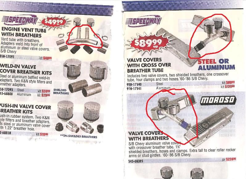
Wonder why no one mentioned doing a mod like this??? I know the space is kinda tight, but we ought to be able to test this one out...
Or maybe putting the catch can in between the 2 valve covers. I think the opening at this junction is actually larger than that in the rear of the driver side and does not have any type of PCV to drill.
What do you guys think?
01-19-2009, 02:39 PM
#139
Registered User
wow this tube is cool !! but as u said it`ll be tight fit, putting a catch can in-line between the valve covers will catch some oil but in the same time oil is going toward the vacuum source so all the oil will still find its way to the Turbo/IC/Engine if u did not use another catch can there.
but as you mentioned here you can use these opening instead of the PCV and the back of the driver side you just need to switch stuff
but as you mentioned here you can use these opening instead of the PCV and the back of the driver side you just need to switch stuff
01-23-2009, 01:45 PM
#140
Anyone willing to give it a try? This is probably the easiest version to try. No Drilling! Just put a 'T' pipe in between the 2 valve cover vents and put a filter on it.
Or:
Just route the oil catch can in between the 2 valve covers with the catch can vented.
Or:
Just route the oil catch can in between the 2 valve covers with the catch can vented.