
Crankcase Ventilation Mod w/Pics


Ditto, I'd like to see some pics of breathers installed directly on the valve cover if anybody has one post up pix or details please.

I think rmedicx suggested utilizing the forward, midline ports that connect the valve covers. I should have this new setup completed this week - should double the flow capacity of usual crankcase evacuation. Will snap a few pics...
Thanks rcdash. Can't wait to see how you plumbed it out. BTW, are you still utilizing the stock plenum. I can see this task being much easier for someone who perhaps has the Kinetix SSV plenum since the front of the stock plenum creates a bit of a narrowing right where you need the mod to work, but I'm sure you can figure this out. Keep us posted.

I will post pics once I start working on it.
Thanks rcdash. Can't wait to see how you plumbed it out. BTW, are you still utilizing the stock plenum. I can see this task being much easier for someone who perhaps has the Kinetix SSV plenum since the front of the stock plenum creates a bit of a narrowing right where you need the mod to work, but I'm sure you can figure this out. Keep us posted.
Why can't we just put a breather on the top of each valve cover? Is it because they're plastic? I had 2 breathers on each side of my viper and 1 on each side of my transam with small K&N filters. I bought them from a parts store and had my shop install them. Of course the valve covers were aluminum but I see no difference. Is there something that requires us to vent from the plenum?
I think it's much better for performance to stop the fuel/hydrocarbons from re-entering the intake side of the engine altogether. I've arranged my PCV setup similar to JetPilots configuration, except that I don't route anything back through the plenum or intake. This might not be the best way on a FI car.
I drilled out my PCV valve as much as possible and run it through a catch can and on to exit under the car... plugged the fitting in the intake tube on the drivers side and currently have the breather from the valve cover releasing to atmosphere. I'm not having much luck finding a 5/8" filter for the driver's side, but I plan to get one once I find one.
So, if the plenum was already out and I had no prob removing my valve covers and drilling/venting is there anything else potentially wrong in an FI'd environment with venting the crankcase this way?
I've read through at least 2 threads were people are trying multiple different ways to vent from the plenum and while I'm definitely not an expert I don't see why somebody hasn't tried this. I'm willing to experiment if I can get some confirmation that this would be an idea route.
The problem I think with the PCV and Plenum mods is that when you're boosting you're creating more pressure in the plenum/manifold due to boost. While it doesn't come close to crankcase pressures it may not be enough to create as much vacuum as there would be in a no boost situation where the lower plenum pressure draws in the crankcase pressure.
The other thing I've noticed is that all the catch cans out there have no filtering. I was thinking of putting an air compressor oil filter in as a catch can. I personally think if there is enough oil blowing by to just "drop" into a can there is serious problems with your cylinders or piston rings. If there is no filter or screen how does a catch can effectively catch the mist of oil in the pressurized air?
Technically, at the end of the day a catch can with a breather will dump ozone anyway so I would really like to vent the valve covers either on the top or on the outer sides with a vent. I wonder if the PCV valve in the Z talks to the EMS though and how I'd trick it if I sealed off the whole PCV/crankcase ventilation system that's built into our car?
Last edited by iamdigital; Mar 30, 2009 at 10:51 AM.


If the PCV doesn't talk to the ECU than could we just put breather filters on the ports and plug the plenum? I still think when boosting at 15-25PSI that there is too much pressure in the plenum/intake manifold to create enough vacuum to effectively alleviate crankcase pressure. Plus this would clean up a mess of tubes around the top of the engine for the crankcase ventilation tubing. I'm just trying to find out if there are any reasons other than emissions why it the pressurized gas has to be recirculated back into the engine.
Also, if you utilize those ports/vents than you wouldn't even have to drill the valve covers. Maybe we could put a draft tube leading to the ground to dump gasses and excess oil mist/blow-by?


Last edited by iamdigital; Mar 30, 2009 at 04:39 PM.

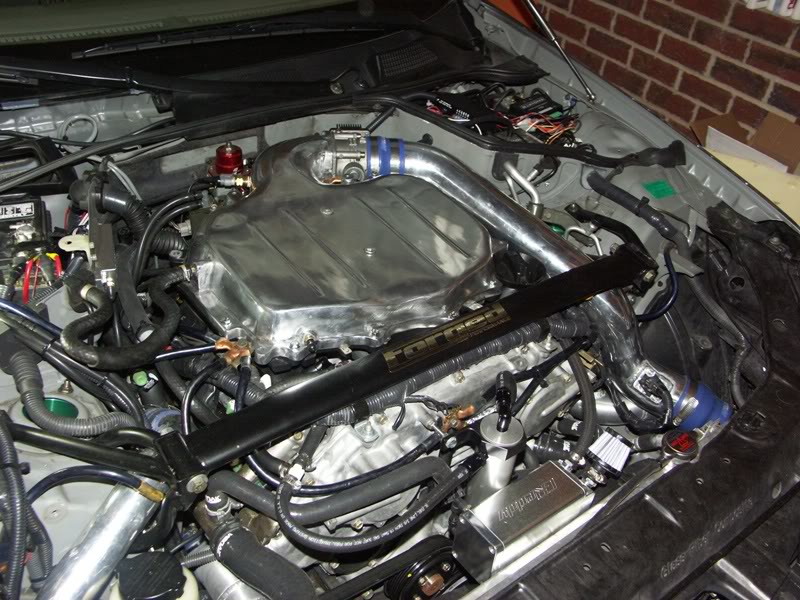
You can see the tubing that joins the valve covers right in front of my plenum. In the lower left hand corner you can see a piece of tubing that goes from the PCV valve out of the picture to my catch can. The drivers side breather is at the back of the valve cover and normally connects underneath the intake tube.
Pay no attention to my brand new, shiny Cosworth plenum...

Aight,
So what I'm gonna fab up is something similar. I'm going to:
1. Plug the plenum
2. Vent the passenger side to atmosphere using a check valve between the catch can (catch can simply there to keep oil spraying over engine bay)
3. Connect the passenger side to the intake tube but put a check valve and filter between there. This is where my concern comes in. Connecting to the intake pipe even with a catch can is gonna let hella oil get in.
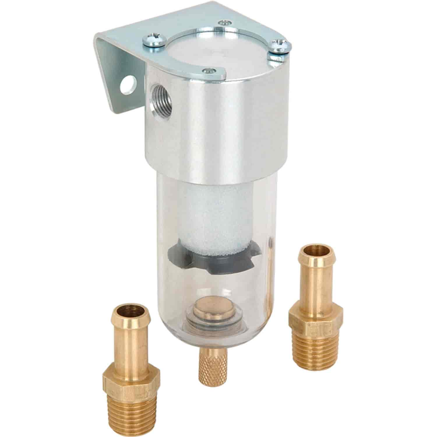
Here is what I was thinking for a filter:
I'd also be concerned with OP's mod as drilling out the PCV doesn't keep a one way or is this a good thing? PCV valve prevents pressure/gasses from going back in correct? Isn't this a need so you don't have a reverse suction?
So what I'm gonna fab up is something similar. I'm going to:
1. Plug the plenum
2. Vent the passenger side to atmosphere using a check valve between the catch can (catch can simply there to keep oil spraying over engine bay)
3. Connect the passenger side to the intake tube but put a check valve and filter between there. This is where my concern comes in. Connecting to the intake pipe even with a catch can is gonna let hella oil get in.
Here is what I was thinking for a filter:
I'd also be concerned with OP's mod as drilling out the PCV doesn't keep a one way or is this a good thing? PCV valve prevents pressure/gasses from going back in correct? Isn't this a need so you don't have a reverse suction?
Last edited by iamdigital; Mar 30, 2009 at 05:44 PM.
You need a check valve to ensure one way flow. The problem with the stock PCV is that it is designed to reduce flow under high vacuum, even if the air flow is in the correct direction. So drill out the PCV and then use a standard check valve.
Here is the point where I tap the valve cover to suck out fumes:

This doesn't quite work because the tee needs to be left or right of center. I need to find 1/2" emissions or fuel injection hose... (sigh)
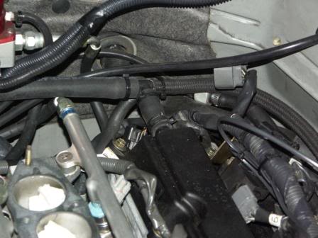
EDIT: ok, finally got this installed...
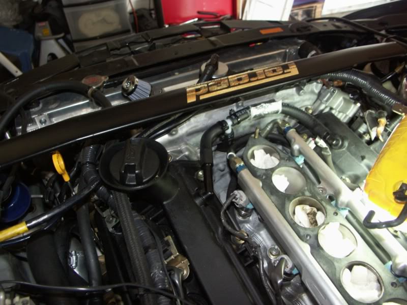
Here is the point where I tap the valve cover to suck out fumes:
This doesn't quite work because the tee needs to be left or right of center. I need to find 1/2" emissions or fuel injection hose... (sigh)
EDIT: ok, finally got this installed...
Last edited by rcdash; Apr 5, 2009 at 10:22 PM.
Updating this thread after receiving a PM. The above worked but is overly complicated and not necessary (for me). I realized this by actually logging crankcase pressure (well catch can pressure actually). I was seeing crankcase pressure as high as 4 psi, running 15 psi of boost for less than 10 seconds, depending on various plumbing configurations! Read on for a method that minimizes this...
My current set up entails having a breather filter on the drilled out PCV nipple on the passenger side. This breather is designed to allow fresh air into the crankcase unless blow by is excessive (happens under extended boost conditions - I've data logged it!). The driver's side valve cover vent has a 1/2" heater hose connection that goes to my single greddy square catch can up front. That catch can is stuffed with a sponge to trap oil vapor and the outlet goes to a tee fitting. One end of the tee has a check valve and goes to the plenum port. The other end of the tee also has a check valve and goes to the driver's side turbo air intake piping (this is required for me because of my recirculating bov that dumps air into that tube on throttle lift).
This set up works well (crank case pressure reaches max 1 psi even with extended boost) and eliminates smoking issues I've had in the past. With the tubing and check valves I have in place I draw about 4-6 mm Hg (2-3 psi) of vacuum during idle, which helps to maintain piston ring seal during idle/low load conditions. I think the mirror image of my current set up will work also (swapping driver's side and passenger's side valve cover functions) but I haven't had a chance to actually test it and data log it. The size and length of tubing used has a direct impact on ability to evacuate crankcase pressure!
Last edited by rcdash; Apr 1, 2010 at 07:23 AM.

Thanks for the update Raj, I am currently working on this. I was planning to use 2 breather filters and NO catch can. I was going to eliminate the PCV, put a breather there and one on the back of the DS valve cover. So i would not be using vaccum to vent the CC has anyone tryed this way or can anyone tell me why it wouldn't work? I see it discussed in this thread but no results.