
wastegate duty vs boost level? what are your #'s


Thread Starter
New Member
iTrader: (11)
Joined: Oct 2007
Posts: 8,807
Likes: 7
From: raleigh-wood NC
Hey guys
Just trying to get an idea about the normal range of wastegate duty used for different setups to achieve your target boost.
If possible could you list:
# of wastegates
Wastegate spring
and wastegate duty cycle to maintain what boost
ie:
2
10psi springs
70% for 17psi.
Thanks!
Just trying to get an idea about the normal range of wastegate duty used for different setups to achieve your target boost.
If possible could you list:
# of wastegates
Wastegate spring
and wastegate duty cycle to maintain what boost
ie:
2
10psi springs
70% for 17psi.
Thanks!

It should also be noted where the boost signal for the waste gate is taken. Some take it at the compressor outlet, some are in the charge pipe before TB, and some will have it at the manifold.
I know that there will be a big difference between those that take it at the compressor vs. those at manifold.
I know that there will be a big difference between those that take it at the compressor vs. those at manifold.
Thread Starter
New Member
iTrader: (11)
Joined: Oct 2007
Posts: 8,807
Likes: 7
From: raleigh-wood NC
what kinda differences? more duty needed by the TB than at the compressor?
I know that raj sees a couple psi drop between compressor and TB, but how does that effect the amount of duty cycle needed?
I know that raj sees a couple psi drop between compressor and TB, but how does that effect the amount of duty cycle needed?

Momentum kit
1 wastegate with 8Psi spring,
18% duty to hold 9Psi boost,
21% for 10,5 at max and 10 at redline.
taken from compressor housing.
1 wastegate with 8Psi spring,
18% duty to hold 9Psi boost,
21% for 10,5 at max and 10 at redline.
taken from compressor housing.
Last edited by chovden; Oct 31, 2011 at 03:35 PM.

Pressure drop across the system. For example, when I had my w/g hooked up to the turbo compressor, my actual boost would go from 8psi (spring) to 6psi by the time I got to red line. MAP sensor is hooked up to the IM. This was with my very first horizontal flow FMIC. The new verticals flow better.
Now with a .6 bar spring (8.82psi) I see a solid 9psi from 3700rpm to red line, without any EBC. I have not used the EBC to go up from there as I am on the stock block. Perhaps in the spring I will bump it up a bit.
You can see that Chovden needs 18% duty cycle just to get 1 more psi because he is referencing at the compressor housing.
Last edited by Boosted Performance; Oct 31, 2011 at 03:54 PM.
Pressure drop across the system. For example, when I had my w/g hooked up to the turbo compressor, my actual boost would go from 8psi (spring) to 6psi by the time I got to red line. MAP sensor is hooked up to the IM. This was with my very first horizontal flow FMIC. The new verticals flow better.
Now with a .6 bar spring (8.82psi) I see a solid 9psi from 3700rpm to red line, without any EBC. I have not used the EBC to go up from there as I am on the stock block. Perhaps in the spring I will bump it up a bit.
You can see that Chovden needs 18% duty cycle just to get 1 more psi because he is referencing at the compressor housing.
Trending Topics


im referencing 2" past the compressor housing and im seeing 9.5psi at redline and 10.5 at 5k rpm. but on waste gate alone which is 10psi spring. I see 9.5 4-6k and 9 @ redline and I have much longer intercooler piping than your kit, since my kit goes under the steering rack and than around the radiator and enters the IC on the passenger side. Map sensor is at intake manifold the little nipple in the front
Either way, it is something I observed when using the compressor port as wastegate reference.
You have a copy of my kit, correct? I think the PTE turbos have the nipple on the compressor at a bad location as far as using it for waste gate reference. I don't think the length of the piping matters all that much, as long as it is large enough to flow what the turbo puts out.
Either way, it is something I observed when using the compressor port as wastegate reference.
Either way, it is something I observed when using the compressor port as wastegate reference.
have you tried getting the reference point from the manifold? I know it will be a super long hose bot might make a difference , or tapping the charge pipe just past the turbo
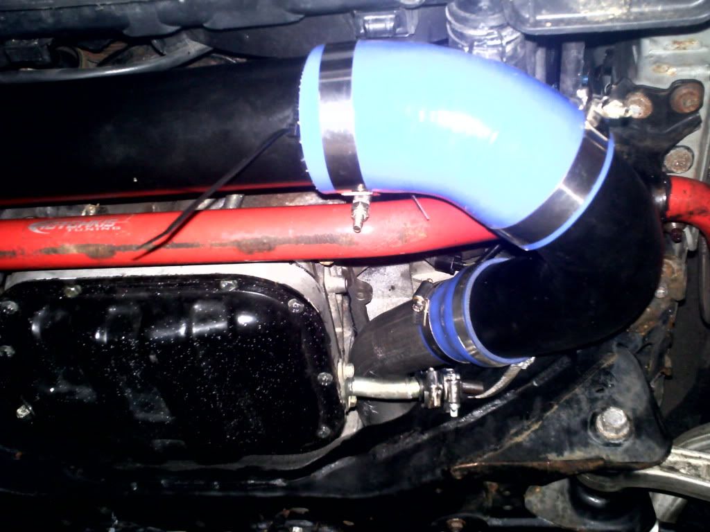
You can see where Precision has the port nipple here:

It turns out that it is not a good place to srource for waste gate reference. With all the kits now, I weld a nipple on the under side of the charge pipe just before the TB.
Rich, sorry for the OT.
i see, good info. I wonder if you could connect the WG of the momentum kit off the intake manifold and see if it would make a difference
It is routed to the manifold (tapped), and the hose is only about 4'. As mentioned, boost stays dead even all the way through to 7000rpm at about 9psi (spring pressure)
You can see where Precision has the port nipple here:
It turns out that it is not a good place to srource for waste gate reference. With all the kits now, I weld a nipple on the under side of the charge pipe just before the TB.
Rich, sorry for the OT.
You can see where Precision has the port nipple here:
It turns out that it is not a good place to srource for waste gate reference. With all the kits now, I weld a nipple on the under side of the charge pipe just before the TB.
Rich, sorry for the OT.


boosted performance 6765
compressor housing
.6 bar (8.82) spring
23% 16psi
27% 18psi
those are in 3rd gear pulls. 4th gear drops them down about 5% duty cycle (logged with my closed loop controller)
compressor housing
.6 bar (8.82) spring
23% 16psi
27% 18psi
those are in 3rd gear pulls. 4th gear drops them down about 5% duty cycle (logged with my closed loop controller)


Thread
Thread Starter
Forum
Replies
Last Post
Colombo
Forced Induction
35
Nov 9, 2020 10:27 AM
ars88
Zs & Gs For Sale
18
Apr 4, 2016 07:52 AM