Forged Performance: rcdash's Twin Turbo G35
#63
Thread Starter
New Member
iTrader: (18)
Joined: Jul 2005
Posts: 6,474
Likes: 65
From: Chapel Hill, NC
Thanks guys. If all goes well, there should be 1 or 2 more surprises before ZdayZ this year.  I hope I don't screw anything up in between now and then - well, I guess that's what Sharif is for.
  I swear after ZdayZ this year, I'm not mod'ing the car anymore. Except maybe for that TS rear diffuser... hmmm... These d@mn forums.
 I hope I don't screw anything up in between now and then - well, I guess that's what Sharif is for.
  I swear after ZdayZ this year, I'm not mod'ing the car anymore. Except maybe for that TS rear diffuser... hmmm... These d@mn forums.
Last edited by rcdash; 02-28-2009 at 11:03 AM.
#64
Thread Starter
New Member
iTrader: (18)
Joined: Jul 2005
Posts: 6,474
Likes: 65
From: Chapel Hill, NC
Here's a few more tidbits I finally got installed. Almost ready for the final few mods... 
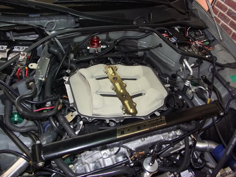
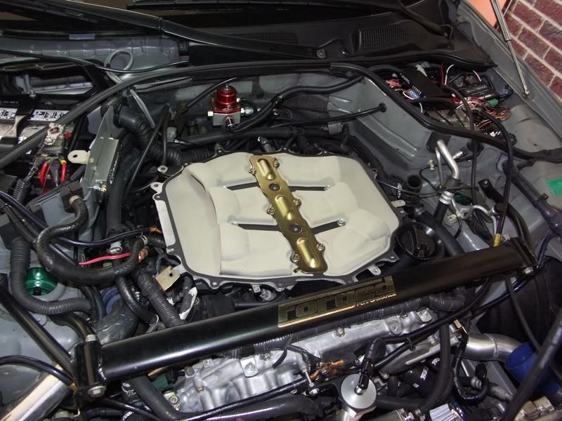
Got the plenum ceramic coated - here's what the inside looks like.
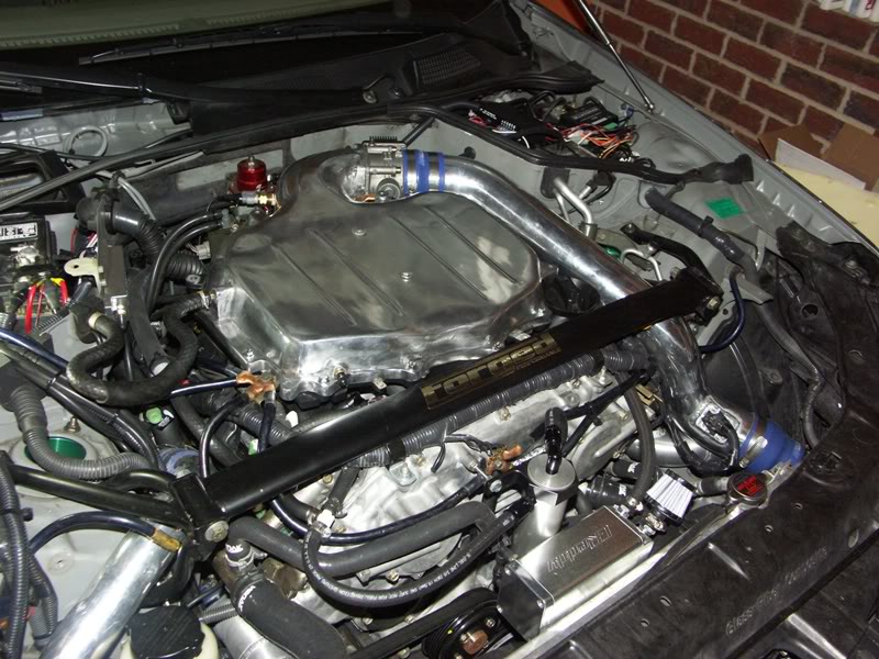
Got the outside polished and also reworked the crankcase ventilation with two catch cans.
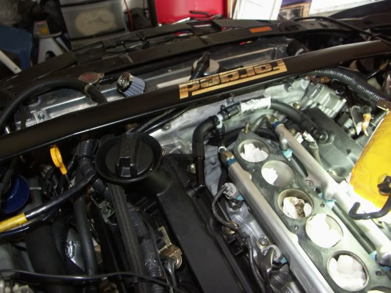
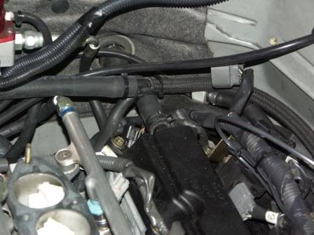
Here's the rest of the plumbing hook up...

Got the plenum ceramic coated - here's what the inside looks like.

Got the outside polished and also reworked the crankcase ventilation with two catch cans.

Here's the rest of the plumbing hook up...


#67
Thread Starter
New Member
iTrader: (18)
Joined: Jul 2005
Posts: 6,474
Likes: 65
From: Chapel Hill, NC
Sure - sorry about that. I'll try to diagram it - hope it helps.
M = Mike Norris catch can is the round one in front of the timing cover
G = Greddy catch can
P = Drilled out passenger side PCV
D = Driver's side rear valve cover vent
C = central valve cover hose that connects passenger and driver side valve covers
> = one way check valve in the direction of the arrow
This is basically what I think you suggested in Jet's thread rmedicx. I haven't tested it thoroughly so I didn't want to post a new thread on it just yet. So far so good though. Boosted 400 miles or so with this setup.
M = Mike Norris catch can is the round one in front of the timing cover
G = Greddy catch can
P = Drilled out passenger side PCV
D = Driver's side rear valve cover vent
C = central valve cover hose that connects passenger and driver side valve covers
> = one way check valve in the direction of the arrow
Code:
P----D----G----open air breather

C----M--|
        |-->---intake manifold (provides suction on decel, off boost)
        |-->---driver's side turbo compressor inlet (for suction during boost)
Last edited by rcdash; 04-24-2009 at 05:45 AM.
#68
Good News. Looking forward to the write up on that too. Thanks for the quick response.
If I understand the schematics correctly you put a Tee in the valve cover connector tube leading to the Mike Norris can. Out from the can you split the line --> one to the turbo intake and the other to the plenum?
If I understand the schematics correctly you put a Tee in the valve cover connector tube leading to the Mike Norris can. Out from the can you split the line --> one to the turbo intake and the other to the plenum?
#69
Thread Starter
New Member
iTrader: (18)
Joined: Jul 2005
Posts: 6,474
Likes: 65
From: Chapel Hill, NC
That is exactly correct. The check valves make certain that the air only goes in the correct direction, OUT of the Mike Norris catch can and either INTO the plenum or INTO the turbo compressor. The other circuit with the Greddy catch can is designed to ventilate air IN, but if blow by exceeds flow capabilities, it is also a safety and can also vent. No check valves on the Greddy catch can plumbing.
Last edited by rcdash; 04-24-2009 at 06:45 AM.
#71
Well it needs to be dialed in like anything else. Has it made the car hook better in lower gears? Not yet but I'm still playing with it. The boost control does work - I've logged boost vs. wheel spin, but there is a delay and the tires still spin, and once they let go, it's harder to get traction back without bogging or upshifting, so verdict still out...  I think timing changes would be instant, so I'm thinking about that route, but want to check with Hal first on that.
 I think timing changes would be instant, so I'm thinking about that route, but want to check with Hal first on that.
#72
Thread Starter
New Member
iTrader: (18)
Joined: Jul 2005
Posts: 6,474
Likes: 65
From: Chapel Hill, NC
Yes, the boost map is based on speed and wheel slip both. Figuring out the right values takes time and changes depending on traction (road condition, tires, etc). The other issue is that boost changes are a bit too slow. By the time you reduce boost, wheels are already spinning. I need another custom map that affects timing also, I think. That would be more immediate and perhaps allow for maintenance of grip.
#73
Yes, the boost map is based on speed and wheel slip both. Figuring out the right values takes time and changes depending on traction (road condition, tires, etc). The other issue is that boost changes are a bit too slow. By the time you reduce boost, wheels are already spinning. I need another custom map that affects timing also, I think. That would be more immediate and perhaps allow for maintenance of grip.
#74
Thread Starter
New Member
iTrader: (18)
Joined: Jul 2005
Posts: 6,474
Likes: 65
From: Chapel Hill, NC

#76
#77
Thread Starter
New Member
iTrader: (18)
Joined: Jul 2005
Posts: 6,474
Likes: 65
From: Chapel Hill, NC
Here is my vid from the ZdayZ Injected Performance dyno session. The exhaust is one of the first production units of the Motordyne TDX with the 2.5" primaries and Shockwave axle back (3" straight pipes, no mufflers, X pipe with resonator). I'll be switching out to 3" primaries and the huge VQ muffler as soon as they are ready. As a testament to the design, even with the 2.5" primaries, it edged out my evoTT for #s. The dyno chart is at the end of the vid (scanned in for clarity). With the shockwave back end, the exhaust is suprisingly only slightly louder than the evoTT despite not having a muffler.
You will note the whine of the new R888 tires - almost exceeds the noise of the exhaust. It's not so bad on the highway, but it seems to come and go. Sharif went to go reassure the dyno crew that it was normal noise for those tires. I also apparently need to stop using my plenum as a vacuum source - note the puff of smoke on decel.
<object width="425" height="344"><param name="movie" value="http://www.youtube.com/v/hF0-HBJEtTI&hl=en&fs=1"></param><param name="allowFullScreen" value="true"></param><param name="allowscriptaccess" value="always"></param><embed src="http://www.youtube.com/v/hF0-HBJEtTI&hl=en&fs=1" type="application/x-shockwave-flash" allowscriptaccess="always" allowfullscreen="true" width="425" height="344"></embed></object>
With some input from the Mad Scientist Jkenefic, here is my planned cc ventilation:
M = Mike Norris catch can is the round one in front of the timing cover
G = Greddy catch can
P = Drilled out passenger side PCV
D = Driver's side rear valve cover vent
C = central valve cover hose that connects passenger and driver side valve covers
> = one way check valve in the direction of the arrow
** the difference here is that the vacuum from the plenum is no longer used which apparently is a bit too strong during decel. We'll see what happens with this new setup next time I dyno (which will be when I get the rest of the Motordyne exhaust components for a before/after)
You will note the whine of the new R888 tires - almost exceeds the noise of the exhaust. It's not so bad on the highway, but it seems to come and go. Sharif went to go reassure the dyno crew that it was normal noise for those tires. I also apparently need to stop using my plenum as a vacuum source - note the puff of smoke on decel.
<object width="425" height="344"><param name="movie" value="http://www.youtube.com/v/hF0-HBJEtTI&hl=en&fs=1"></param><param name="allowFullScreen" value="true"></param><param name="allowscriptaccess" value="always"></param><embed src="http://www.youtube.com/v/hF0-HBJEtTI&hl=en&fs=1" type="application/x-shockwave-flash" allowscriptaccess="always" allowfullscreen="true" width="425" height="344"></embed></object>
With some input from the Mad Scientist Jkenefic, here is my planned cc ventilation:
M = Mike Norris catch can is the round one in front of the timing cover
G = Greddy catch can
P = Drilled out passenger side PCV
D = Driver's side rear valve cover vent
C = central valve cover hose that connects passenger and driver side valve covers
> = one way check valve in the direction of the arrow
Code:
P----D----G----open air breather

C----M--|
        |-->---driver's side turbo compressor inlet (for suction during boost but also is spooled on decel so continues to provide suction)
#79
Thread Starter
New Member
iTrader: (18)
Joined: Jul 2005
Posts: 6,474
Likes: 65
From: Chapel Hill, NC
Thanks James. My goal with going with the Motordyne is to be able to run most of the time with the near silent VQ muffler and still attain close to 600 DJ whp with W/M injection. We'll see how that goes as soon as those components come in...
Here's some pics of the exhaust, first from Motordyne website:

And now some installed on my car!
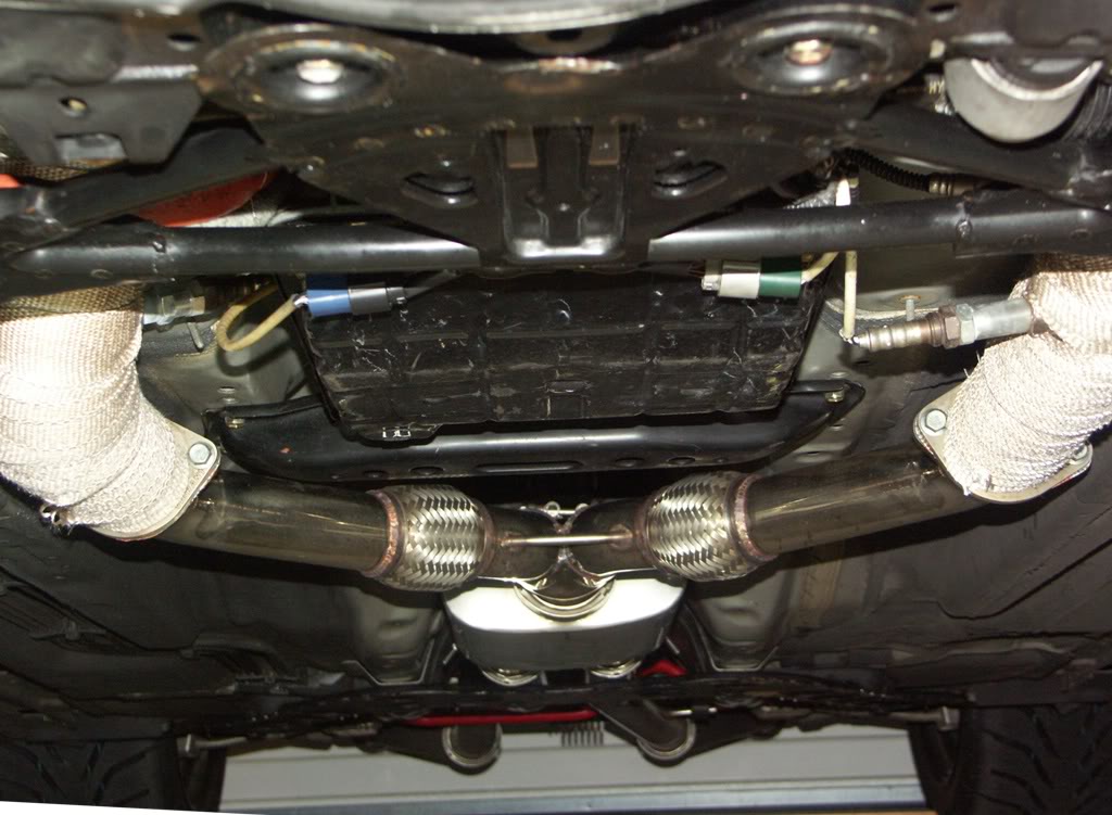
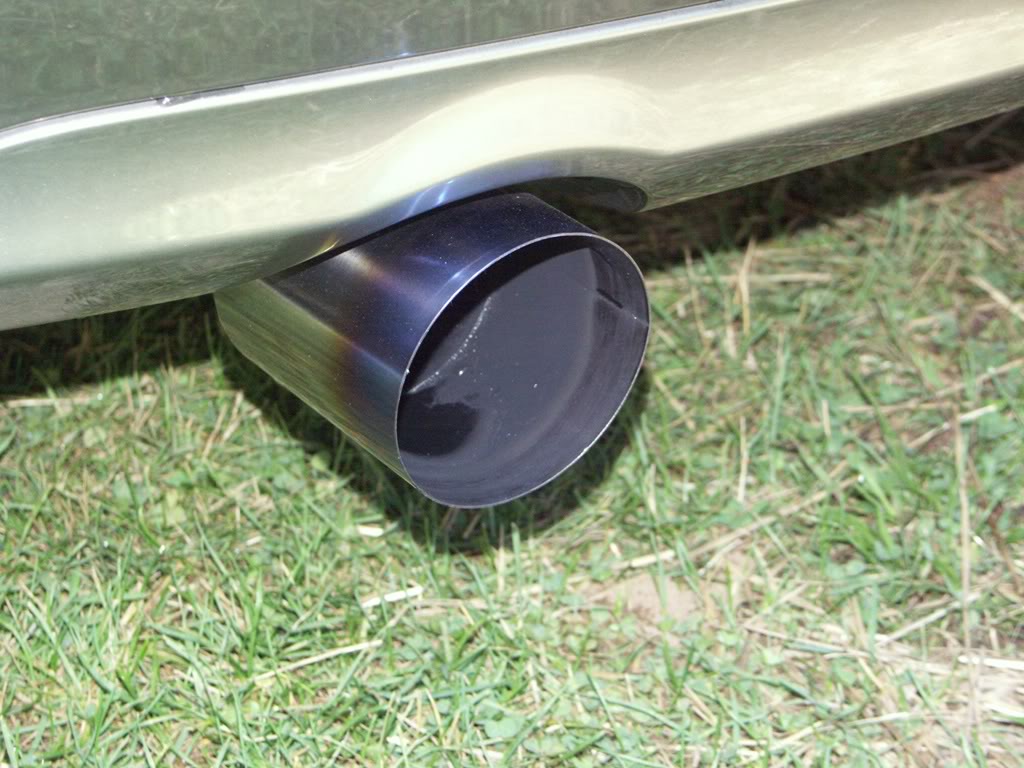
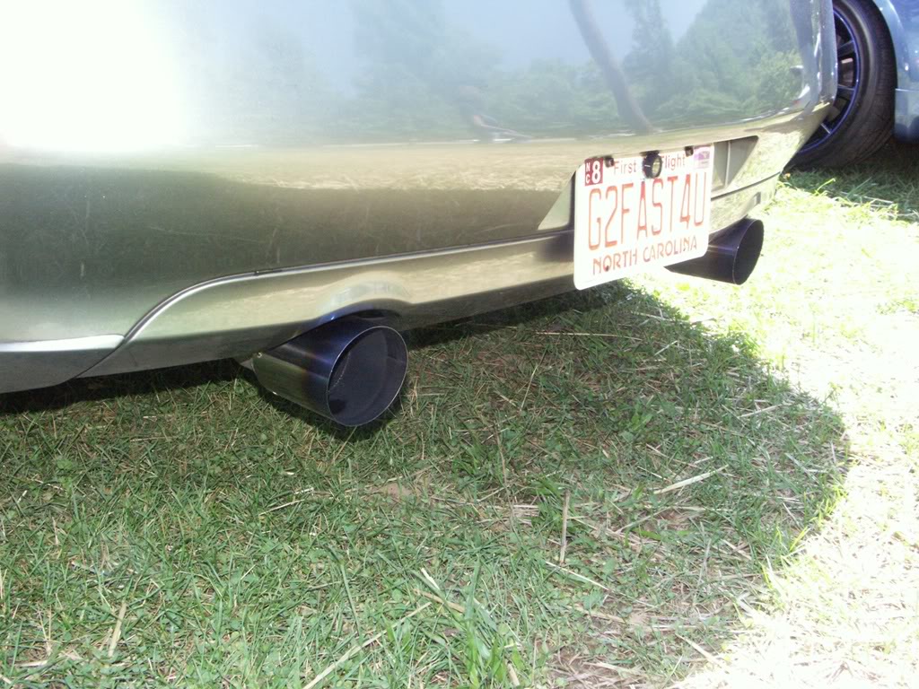
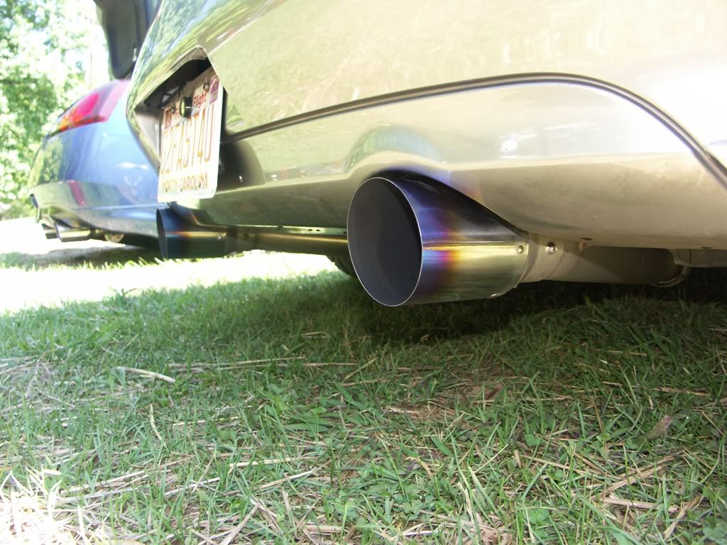
Here's some pics of the exhaust, first from Motordyne website:

And now some installed on my car!


Last edited by rcdash; 06-10-2009 at 04:40 AM.
#80
Thread Starter
New Member
iTrader: (18)
Joined: Jul 2005
Posts: 6,474
Likes: 65
From: Chapel Hill, NC
Catch can routing updated as I was seeing smoke on decel and catch can was filling up too rapidly. I opened up plenum to find oil in the center section. So I sealed off the plenum by extracting the nipple in the front (almost sheared it off trying to get it out), drilled out with 1/8" NPT tap, and sealed up with a 1/8" NPT plug.
At ZdayZ I hit transmission temps of 290 deg F while driving with the Mad Scientist in the car, trying to keep up with Sharif's GTR.  Completely unacceptable - had to shut it down. I realized later that that may be falsely elevated due to my temp sensor being located before the cooler (right after the torque converter) rather than in the transmission pan or after the cooler. I was very concerned that my current trans cooler was not up to the task.
So I updated my trans cooler from this:
B&M BMM-70264: Fluid Cooler, Transmission, Plate-Type, Aluminum, Black, 6 in. x 11 in. x 1 1/2 in, rated 14,400 GVW

to this:
Tru Cool 4590 - 48 plates, rated at 28,000 GVW and measures 11"x11"x.1.5".

Temps have dropped an average of 40 degrees F! Daily boosting keeps temp well under 190 F. Nice! I HIGHLY recommend this specific trans cooler to all FI 5AT owners. You can get it to fit snugly on the passenger side in front of the radiator. It covers the entire passenger side of the radiator and it's a tight fit, but it fits!
Code:
Mike Norris catch can[/URL] is the round one in front of the timing cover
G = Greddy catch can
P = Drilled out passenger side PCV
D = Driver's side rear valve cover vent
C = central valve cover hose that connects passenger and driver side valve covers
> = one way check valve in the direction of the arrow

P----D----M--->---driver's side turbo compressor inlet
(for suction during boost but also is spooled on decel so continues to provide suction, just not as much as plenum, which is now sealed off)

C----G---open air breather
(to allow air in for ventilation and additional route for gas escape during high load conditions)
So I updated my trans cooler from this:
B&M BMM-70264: Fluid Cooler, Transmission, Plate-Type, Aluminum, Black, 6 in. x 11 in. x 1 1/2 in, rated 14,400 GVW

to this:
Tru Cool 4590 - 48 plates, rated at 28,000 GVW and measures 11"x11"x.1.5".

Temps have dropped an average of 40 degrees F!
Last edited by rcdash; 08-23-2009 at 12:31 PM.


 NICE!
NICE!