When you click on links to various merchants on this site and make a purchase, this can result in this site earning a commission. Affiliate programs and affiliations include, but are not limited to, the eBay Partner Network.
EDIT: I added some additional photos of the dismantle process. I shot these while doing the post-mortem on the alternator I replaced (yes I'm also rebuilding that one to have a spare on the shelf!)
I wanted to create a quick guide on how to rebuild the OEM Mitsubishi Alternator. As many of you may know, aftermarket replacements tend to be unreliable. More often than not, these are poorly rebuilt/remanufactured units where the internal replacement parts are of sub-standard quality. They are also still fairly expensive, expect to spend around $250+ for a typical aftermarket unit. A brand new OEM unit costs over $500.
The benefits of rebuilding the unit yourself is primarily cost savings. For a few hours of your time, you can save hundreds. You can also ensure the quality of the replacement parts and workmanship is above board. This was my 1st time ever rebuilding an alternator, it was a fun learning experience while also saving some cash. I'm also a bit OCD about my Z and I want to keep items like this as original as possible.
In my case, the alternator bearings were in the early stages of failure. Symptoms were intermittent buzzing, I was able to confirm the alternator was the source using an automotive stethoscope. It's sometimes difficult to determine alternator noise from normal power steering pump noise (they are mounted next to each other). The charging system itself was working without issue, meaning the rectifier, stator coil, rotor, and voltage regulator/brushes were all in good working order. The process to remove/swap alternators is quite involved, so instead of rebuilding the unit already in my Z, I pulled the old one off my spare engine and rebuilt that one to minimize downtime. My old Z's alternator has 106k miles on it and was working perfectly up until my old Z met it's end. I could have slapped this unit in the vehicle as is, and been confident it would work. However, there's no telling how many more miles it would last, most likely the bearings would go soon.
Components to consider when Rebuilding an Alternator:
1) Bearings (common failure item)
2) Voltage Regulator/Brush Assembly (common failure item)
3) Rectifier/Diode pack (rare failure item, depends on conditions)
4) Slip Rings (rare failure item, depends on conditions)
5) Stator coil (should be tested with multimeter prior to rebuild)
6) Rotor (should be tested with multimeter prior to rebuild)
If you have a bad stator or rotor, the unit is essentially junk unless you can find a good/cheap replacement part (say from a junk yard!). The stator and rotor are the most expensive components of an alternator. It is rare when these components fail. It would take major debris or heat for one of these to break. Items worth replacing are bearings, voltage regulator/brushes, slip rings, and the diode pack. Depending on the running conditions of the alternator, it's also rare for the slip rings or diode pack to fail or wear out. It would take prolonged periods of non-ideal operating conditions such as exposure to a combination of mud, water, dust, and oil. Also extreme heat or salted roads. Note: There are plenty of guides/videos on YT covering alternator components, how they work, how to test them, etc. If you're interested in rebuilding an alternator, I highly recommend doing some homework on these before proceeding.
In my scenario, I ordered replacement bearings, voltage regulator/brushes, and slip-rings. I ordered the parts before tearing down the unit for a close inspection, but the parts are cheap enough that it's worth spending the extra cash (just in case). There are a few reputable online retailers who sell these parts. The vendor I chose was Maniac Electric Motors. Here's a LINK to the 350Z/Mitsubishi unit parts page. The listing says 03-06, but I assume this also covers 07-08 Z & Gs with the HR.
Rebuild Process...
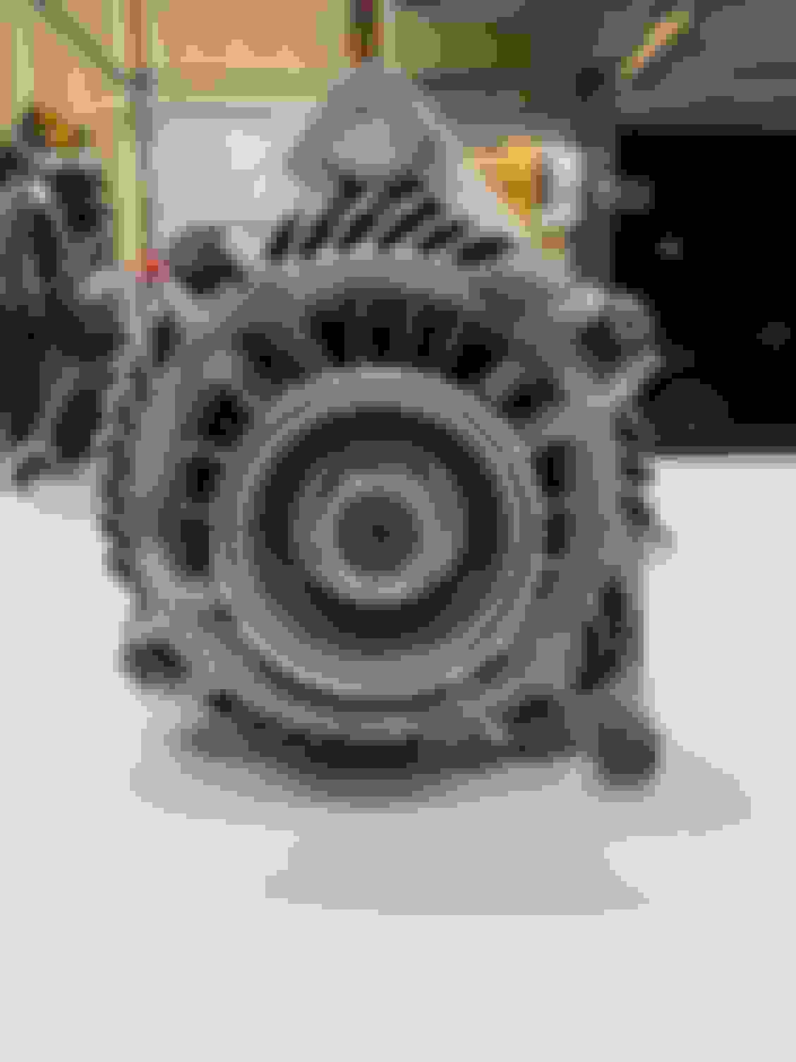
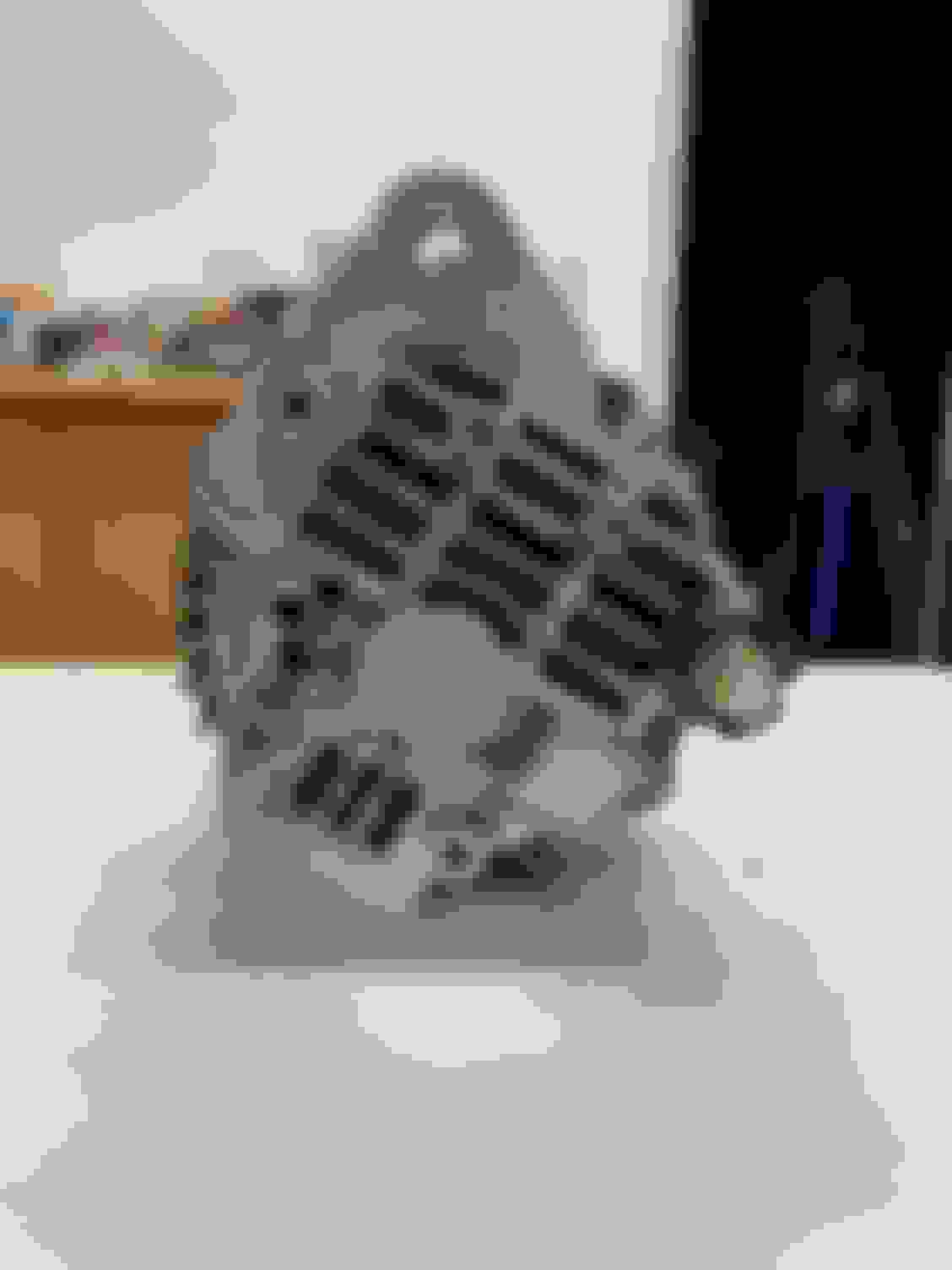
Hit all the body bolts, screws, pulley nut, and stator band (center piece where aluminum casing attaches) with some WD40. Front View - Notice 4x8mm perimeter bolts Rear View Side view
Crack and remove all the 8mm perimeter body bolts.
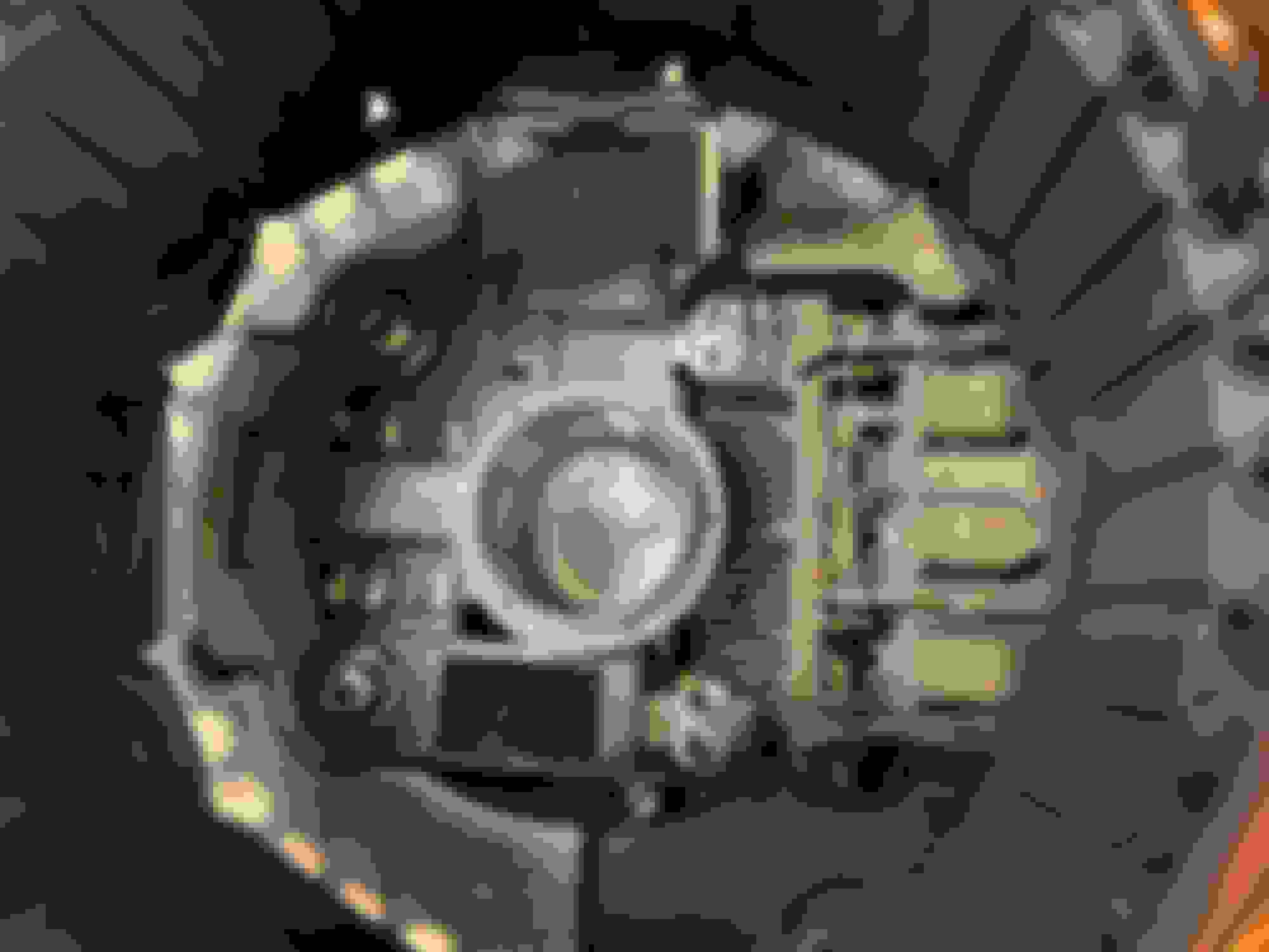
Grab a hammer, preferably a dead blow hammer to prevent marring the aluminum casing and start tapping against the front casing ears. The goal is to separate the rear bearing from the rear casing. The entire rotor and front casing should separate. Casing separated, rotor with front case. Note: I removed the pulley 1st, but the rust kept the rotor with the front casing during separation, Note the rear shaft bearing with blue seals.
Once the rotor has been removed, you can proceed with removing the pulley & nut (24mm). I used a 3/8" impact with a conversion adapter to 1/2" since I don't have a 24mm 3/8 socket. With a little WD40 assistance, the nut broke free, but it did require some persistence. I highly recommend using a 1/2" cordless impact, the nut should zip right off without any trouble.
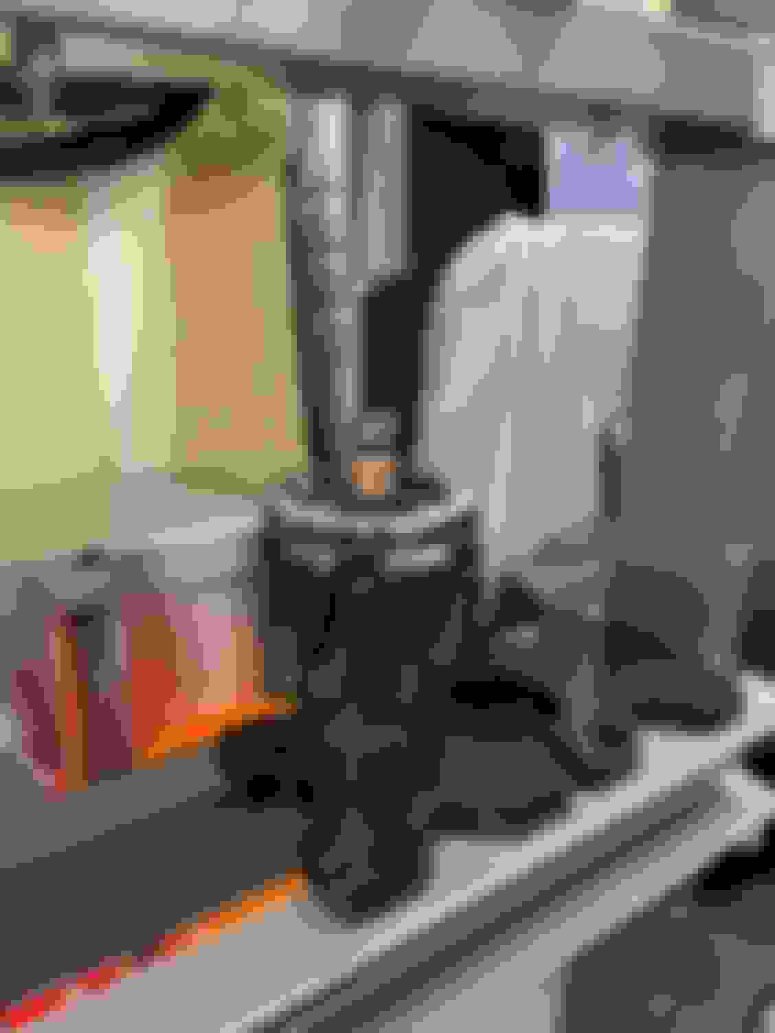
With the pulley removed, add some WD40 to the rotor shaft where it slides through the main bearing. If you're lucky a few light taps with a hammer will separate the rotor from the main bearing. In my case, I have an arbor press, so I used that instead. Some rust/corrosion had formed around the front shaft, gluing it in place. You do not need to press the new bearing onto the rotor, it's a slip fit (tight, but should slide right on).
Pressing the rotor shaft out of main bearing.
Note the rust! Hence the need to use some WD40 or other penetrating oil.
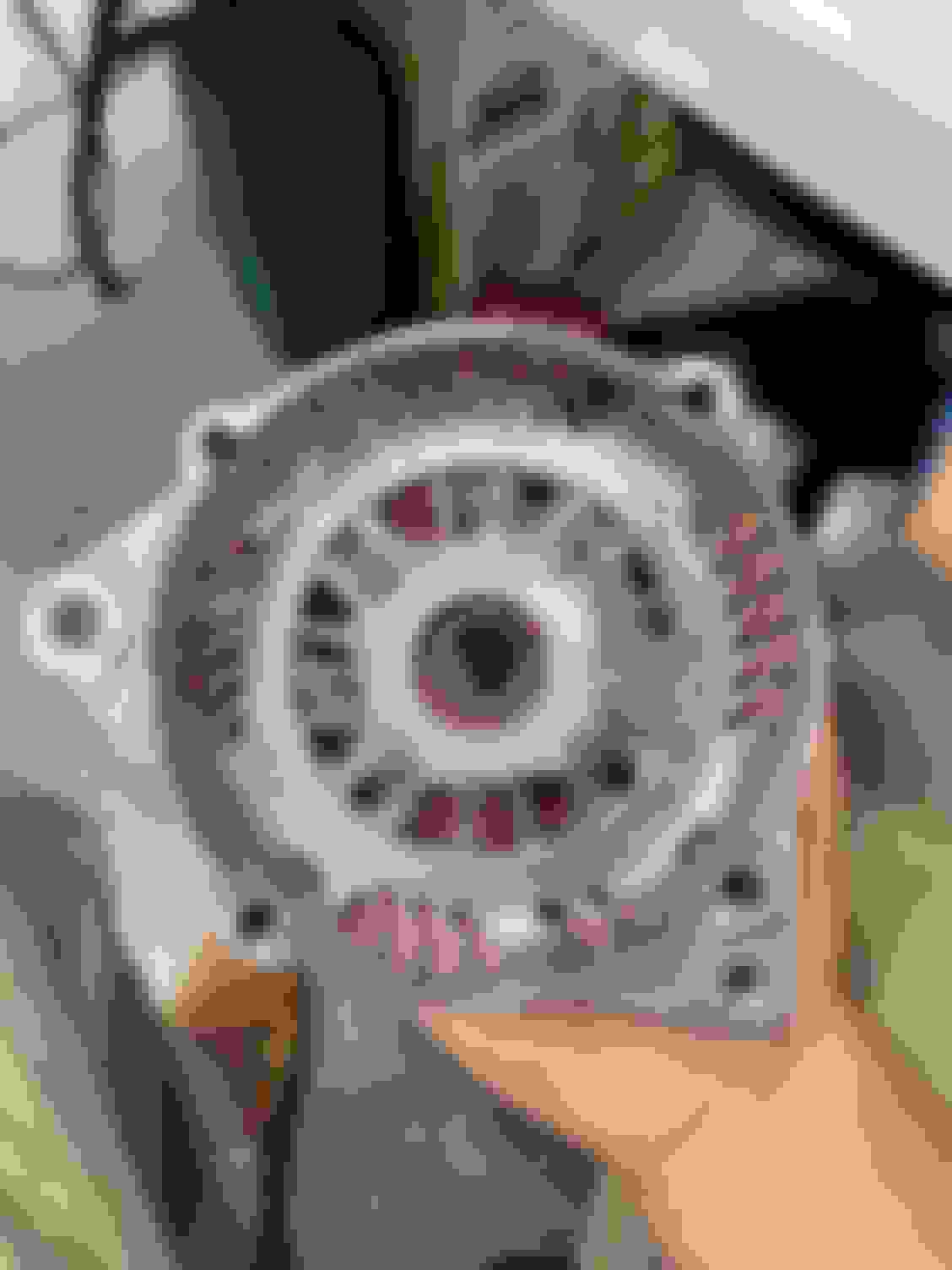
Once the front case has been separated from the rotor, you need to remove the front bearing. The front bearing is captured by a plate with 4xScrews. Crack these loose, I was able to do it with a hand screw driver, no issue, but an impact would be a good idea. Once the capture plate has been removed, you can simply tap out the bearing with a hammer and socket. I used my press.
Rear bearing plate and more rust on inner bearing race.
Pressing out the main bearing from the front case.
Removing the rear bearing from the rotor shaft is more of a challenge. Typical automotive pullers are too large, the claws can't fit in the gap to get a good bite. I had to be a little creative and used my ball joint separator. I added a small 4mm 1/4" socket to press against the shaft. This did the trick, very clean, no damage was done to the shaft or slip rings.
Home-brew bearing puller. Just a cheap Harbor Freight ball joint separator. Works great!
Bearing removed, I needed to add a longer socket/bit to get the last few mm of the bearing off.
With both bearings removed, you can move onto removing the stator from the rear casing. It's held in place by a 12mm nut from the rear battery post & 3 philips screws. Two of the screws are easy access, the 3rd one is half hidden by the stator coil itself. To safely gain access, you will need to loosen everything else up and slightly bend the stator coil assembly away from the casing. There is a cut-out on the casing to assist with access. Just be careful not to scratch or mar the surface of the copper coils/windings. There is a protective coating on the the copper wire which acts as an electrical insulator. Damaging this could ruin the entire stator!
3 Screws visible at this angle.
With the alternator mostly disassembled, you can start the cleaning process of all the pieces. I like to use gasoline and various brushes. To get the really caked on stuff, I use a fine steel bristle brush. Here's how the cleaned up parts came out.
Inside view of inner and outer casing.
All parts cleaned up. New replacement parts also shown.
I'll continue in more detail for Part II - Reassembly. My apologies for lack of detail on some steps. I'm short on time and will need to polish/edit the post later.
Cheers!
-Icer
Hey Icer- your thread was moved to the DIY section as it belongs there. The content is more advanced than most of the threads in the maintenance section.
This is a great write up, thank you. My alternator has just started playing up, working fine when it's cold but failing to charge once it is upto temperature so I'm plannig to rebuild it for the reasons you've listed. I look forward to the next part of the guide. Great photos too!
Hey Icer- your thread was moved to the DIY section as it belongs there. The content is more advanced than most of the threads in the maintenance section.
Thanks dkmura! I realized after posting, that I should have filed this thread in a different category.
The truth is that most ASE certified techs utilize the "repair/replace" factory approved philosophy. This has been going on for decades and 99% of pros don't even try to rebuild alternators..
I left off with parts cleaning in preparation for re-assembly. But I forgot to go into details around the stator cleaning process. It's not essential to clean up the stator, but I'm OCD about the work I do and I wanted mine as clean as possible while still being safe. But I'm getting ahead of myself, since I was replacing the entire voltage regulator and not only the brushes, I unsoldered the unit from the diode pack. This process was a little tricky since the solder is old and a little dirty, getting good heat transfer from my bench solder iron proved difficult (also my tip was a bit small for this application), so I resorted to using my hot air station (set to 750*F), this did the trick. One important item to note is that the voltage regulator is not only soldered to the stator's rectifier/diode-pack, but there's also some locking tabs bent around the regulator's solder bars. These need to be bent back with needle-nose pliers or screwdriver to fully release the regulator/brush assembly.
Here's how it turned out once separated. Regulator separated from stator & diode pack.
With that done, I bagged and taped up the diode pack (don't want that component getting wet!) and gave it a good cleaning with a mild all purpose cleaner (specifically Meguiar's D101). I used a soft detailing brush to get into the tight spaces and remove as much loose dirt/dust as I could. Then simply rinsed with water all while making sure I didn't get any water inside plastic wrapped diode pack. Once I felt the unit was as clean as I was going to get it, I removed the plastic bag and put it in the oven set for convection bake (175*F) for 1.5 hours to make sure it was bone dry. With the unit removed from the oven, I let it cool down overnight. The next day I masked off most of the stator and diode pack and gave the inside of the unit a few licks of some flat black paint. This step is not required, but I noticed the original paint had a few knicks and chips during the rotor removal process. The paint helps with rust/corrosion prevention, no need to go nuts with it. If you decide to paint an alternator, it is recommended to use high-temp rated paint as these things can run around 200*F under load.
Full disclosure: I jumped the gun and painted with standard Rustoleum flat back since that's what I had on my shelf. The label says not to paint items that exceed 200*F, and it is possible that alternators can run hotter than that, plus the unit on the Z is very close to the bank 1 exhaust manifold. So far (knock on wood) this hasn't been an issue. I've given the Z a good test drive since and no issues with the paint spontaneously combusting.
While the stator paint was curing, I used the time to press in the new bearings. Pretty straight forward process, but same results can be achieved with a hammer and steady hand..
Pressing rear shaft bearing.
Quick Note: I forgot to mention this during the cleaning process, but I used a combination of Green and Gray Scotch pads to clean up the rust on the front case (bearing mating surface), the rotor front shaft, and the slip rings. Seeing this picture reminded me of that. There was no need to replace the slip rings, the original ones were still in perfectly good condition, the wear on them was so slight that I would need to break out the calipers to measure it (maybe a few thousandths of an inch). These will easily last another 100k mi of use or more.
Pressing front/main bearing.
Bearing plate re-installed.
Pressing the bearings in went quickly and smoothly. I used a very thin layer of Honda UREA grease on the bearing mating surface of the front casing. This isn't required, but I felt a thin layer of grease might help control rust/corrosion. I wouldn't recommend doing this on exposed surfaces since grease would just attract more dirt, but since the bearing is captured behind a cover plate, this shouldn't be an issue.
After letting the paint cure for the appropriate amount of time, I could move onto soldering the new regulator/brush assembly. This is best done with the stator secured into the rear alternator case. I used the rear battery post 12mm nut and hidden philips screw to achieve this. Alignment of these components is critical since the rotor shaft, bearing, and slip ring assembly need to be centered with the brush assembly. I also prepped both the brush assembly solder bars and diode pack bars with fresh high-grade Kester solder. This helps with heat transfer and ensuring you have a strong and solid solder joint (no air bubbles or gaps). I dropped in the new regulator and loosely installed the philips screws to ensure alignment, then with one hand I used my hot air wand and in the other, a flat blade screwdriver to apply pressure, making sure both bars were fully seated. Here's the end result.
Quick Note about the battery post 12mm nut. Be careful when installing the plastic insulator. It's PLASTIC, don't over-tighten this or it will crack/shatter. The FSM doesn't have a torque spec mentioned for this, so just make it firm/snug, no need to overdo it. There's also an alignment peg on the insulator, making installation orientation self-explanatory.
New regulator/brush assembly soldered in place. Screws all tightened down.
Nearly done, but before you can install the rotor, you need to hold back the brushes (spring loaded), that's what the holes in the brushes are there for. There's a pinhole on the back of the alternator case to allow for securing the brushes in a retracted state. Use anything small and rigid that will fit. In my case, the new brush assembly came with a piece of wire already in place, I just re-used that. Simply push the brushes back into the regulator with a screwdriver while aligning/inserting your pin implement.
Wire inserted on back of case to hold brushes.
Brushes secured.
Now you're ready to install the rotor and front case. Once again I used my press, but you can easily do this with a dead blow hammer. The rear bearing isn't nearly as tight a fit as the front bearing. I pressed until I noticed resistance. Be mindful when pressing the rotor into the rear case, you don't want overdo it (go to far) or damage the new paint. There is a fan blade assembly at the back of the rotor which could start rubbing the diode pack if you bottom out. This happened to me and I was worried at 1st, but it does appear that this is corrected when you install the pulley nut.
The rest is pretty straight forward. Slip the front case over the shaft, it's a tight fit, but the bearing should slip over the front shaft without the need to hammer or tap it down. DO NOT forget the spacer washer that sits between the bearing and front rotor fan-blade. Make sure the front and rear cases are aligned (you can use the main mount bolt as a guide) and install the perimeter case bolts. NOTE: The 8mm case bolts should be torqued to 39-in/lb. Once that's done, install the pulley and nut. The pulley nut should be torqued to 87-ft/lb. It's nearly impossible to hold the pulley/rotor from spinning and achieve that amount of torque with a wrench. I used my neighbors 1/2" air-impact and gave it maybe 8-10 uga-dugas. Once the nut was torqued down, the rotor was spinning smoothly without any rubbing or interference issues.
Here's the end result.
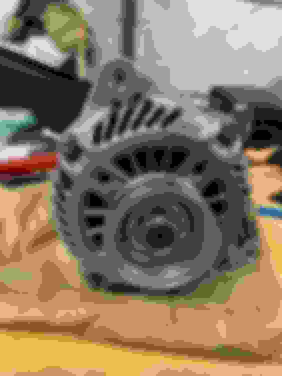
Alternator fully assembled - front view. Rebuilt next to old unit - side view.
Now, I trust my work, but given that installing an alternator on a 350Z is a fairly involved operation, I wanted to be 100% sure everything was good to go. I took my rebuilt unit over to the local auto parts store for a quick bench test. Here are the results.
Alternator Test - PASS!
With the fruits of my labor confirmed, I began the swap process. For the most part, everything went smoothly....except for when I started filling up the radiator with coolant and realized I had forgotten to re-attach the upper rad-hose! There was some coolant spillage and cursing, but I got it all cleaned up and taken care of. Coolant topped off, burped, and test driven. Everything smooth! No more alternator bearing noise. WIN.
Cheers!
-Icer

 09-30-2024 | 11:30 PM