
The problem with catch cans and the 350Z


Thread Starter
New Member
iTrader: (2)
Joined: Sep 2011
Posts: 1,751
Likes: 7
From: Oregon from England
Just tried fitting the can tonight, slightly disappointed it didn't fit right in. Just checking some things with Saikou Michi at the moment, will update as soon as i get info.
The inlet and outlet angles are perfect, should allow for some very nice/short pipe routing. Everything but what i believe to be the height of the bracket is right.
The inlet and outlet angles are perfect, should allow for some very nice/short pipe routing. Everything but what i believe to be the height of the bracket is right.

Drill out PCV valve, connect hose going to a catch can vented to atmosphere, cap off where the old pcv hose goes to i/m.
The other valve cover goes to the intake pipe, take that hose off intake pipe, either hook up to same catch can (dual) or another can, then cap off the intake port.
This is how my car is setup. I could be wrong but this setup is a good way to do it.
The other valve cover goes to the intake pipe, take that hose off intake pipe, either hook up to same catch can (dual) or another can, then cap off the intake port.
This is how my car is setup. I could be wrong but this setup is a good way to do it.


Why hello again everyone.. glad everyone is well tonight..
Id simply like to submit that I am.helplessly lost, completely bewildered, and have fully given.up.on following any of this..haha..
Holy ****... u guys r outta control..
Fantastic thread tho.. this is the thread type and knowledge base I LOVE to see n read n absorb ..
But holy *****..I get these reply emails on my phone and am so lost that its incredible haha..

How so? The PCV side has vacuum from the intake, behind the TB, it's constant and heavy.
The drivers side just has the intake air blowing that way.
Independent PCV articles show the same thing, seems no one shows it the way you're describing.
I do however think, that i know what you're saying about the intake pipe, wind rushing past the end of it should technically create a vacuum at the intake tube end. However, it has to suck air from somewhere, the PCV valve is one way, so it can't travel that way.
Plenum pulls from the PCV side/passenger side.
Engine pulls from the drivers side/intake tubing. The system is sealed, the intake speed would have to create a vacuum waaay more powerful than the one the plenum is creating (on the other side) for it to be flowing back into the intake tubing.
You don't get oil on the front side of the butterfly, just the back side.
It's unlikely to be pushed, now you make me think about it, see last comment i made as to how that flows.
Not really sure what you mean about buying a Bosch oil filter, i use them all the time...
Yeah, i would imagine it is, they all use the same system, nearly (if not actually) all modern cars use the sealed PCV system.
on a side note what bosch oil filter did you find that fits?
edit: oh yah i dont have the tube anymore from the stock intake since the turbo kit replaced that but mine most definitly was saturated with oil around the port for the driver side valve cover and i had to clean the oil off both sides of the throttle plate(since my pcv system was venting to atmosphere without a can haha i was too lazy to hook it up knowing it was just coming right back out.)
Last edited by jerryd87; May 30, 2012 at 07:11 PM.
Thread Starter
New Member
iTrader: (2)
Joined: Sep 2011
Posts: 1,751
Likes: 7
From: Oregon from England
Drill out PCV valve, connect hose going to a catch can vented to atmosphere, cap off where the old pcv hose goes to i/m.
The other valve cover goes to the intake pipe, take that hose off intake pipe, either hook up to same catch can (dual) or another can, then cap off the intake port.
This is how my car is setup. I could be wrong but this setup is a good way to do it.
The other valve cover goes to the intake pipe, take that hose off intake pipe, either hook up to same catch can (dual) or another can, then cap off the intake port.
This is how my car is setup. I could be wrong but this setup is a good way to do it.
However, i would think that all you've done is replaced a very 'flowing' efficient method of removing the corrosive crank gasses and replaced it with something less efficient than the original draft venting system used in the 50's.
Also, the only point of the catch can is to stop/catch the oil in gas form and stop it going back into the engine's breathing system. If you've removed that connection, then the can is only there to catch incidental release.
Last edited by F2CMaDMaXX; May 30, 2012 at 07:32 PM.
Thread Starter
New Member
iTrader: (2)
Joined: Sep 2011
Posts: 1,751
Likes: 7
From: Oregon from England
the point i was making with the bosch oil filter is everywhere i have went to buy them bosch hasnt had a oil filter for our car and the listing they have had have been a oil filter with double the body size and a smaller thread interesting you found one that fit since the 2012 book i just looked in the other day had the wrong filter, so did the 2011 can 2010 books that the stores still had, in fact when they looked it up in there computer it said it did not fit and bosch made none.
 is it a problem on the island trying to get it? I'm sorry i don't have the box or a picture of such handy, i use the book in my local autozone. The Bosch website lists the 3300 version for my '04, and as my memory recalls, that sounds about right. My local autozone doesn't keep many of them.
edit: oh yah i dont have the tube anymore from the stock intake since the turbo kit replaced that but mine most definitly was saturated with oil around the port for the driver side valve cover and i had to clean the oil off both sides of the throttle plate(since my pcv system was venting to atmosphere without a can haha i was too lazy to hook it up knowing it was just coming right back out.)
Turbo's are quite different in setup, they cause reverse flow in the first pipe, the one from the drivers side to the intake tubing. Best to have a catch can there as well if turbo'd.
On an N/A engine, it's one way, under any partial throttle condition, there is leakage the other way, full throttle condition, but it's still limited. This is also detailed in the FSM.
For reference purposes, for others, i'll just drop that pic down below.
Of note, is the amount of available vacuum at full and partial throttle conditions, again to do with the Bernoulli principle, as the connection from the intake tube to the drivers side is a few inches away from the butterfly. The return loop into the plenum, after travelling through the engine, is only a few inches on the other side of the butterfly.

Last edited by F2CMaDMaXX; May 30, 2012 at 08:01 PM.
Thread Starter
New Member
iTrader: (2)
Joined: Sep 2011
Posts: 1,751
Likes: 7
From: Oregon from England
Yeah, seen the home made ones. Always dubious of the not for oil use on them and the lack of baffling. But all reports i've seen, show them lasting a while. Still they're better than nothing  Just watch for the pressure/vacuum causing leaks in some of them.
Just watch for the pressure/vacuum causing leaks in some of them.
I'm sure there is a small one, the Bernoulli principle takes care of that.
It's not really open, it has an idle bypass, but there is some movement. Remember the engine is only sucking a small amount at this point and the movement of air in the intake tubing is very low.
You're describing two different things here, it's either using the Bernoulli principle, or it's not. The manual describes flow from the intake tube, to the drivers side cover. But you just described it to go the other way. You also confirmed it's not setup that way, therefore the flow must be the other way, the way in which everyone else describes PCV flow.
That sucks, really is it a problem on the island trying to get it? I'm sorry i don't have the box or a picture of such handy, i use the book in my local autozone. The Bosch website lists the 3300 version for my '04, and as my memory recalls, that sounds about right. My local autozone doesn't keep many of them.
Yeah, no kidding, experienced plenty of stuff like that, usually worse with model refresh years.
Turbo's are quite different in setup, they cause reverse flow in the first pipe, the one from the drivers side to the intake tubing. Best to have a catch can there as well if turbo'd.
On an N/A engine, it's one way, under any partial throttle condition, there is leakage the other way, full throttle condition, but it's still limited. This is also detailed in the FSM.
For reference purposes, for others, i'll just drop that pic down below.
Of note, is the amount of available vacuum at full and partial throttle conditions, again to do with the Bernoulli principle, as the connection from the intake tube to the drivers side is a few inches away from the butterfly. The return loop into the plenum, after travelling through the engine, is only a few inches on the other side of the butterfly.
It's not really open, it has an idle bypass, but there is some movement. Remember the engine is only sucking a small amount at this point and the movement of air in the intake tubing is very low.
You're describing two different things here, it's either using the Bernoulli principle, or it's not. The manual describes flow from the intake tube, to the drivers side cover. But you just described it to go the other way. You also confirmed it's not setup that way, therefore the flow must be the other way, the way in which everyone else describes PCV flow.
That sucks, really
is it a problem on the island trying to get it? I'm sorry i don't have the box or a picture of such handy, i use the book in my local autozone. The Bosch website lists the 3300 version for my '04, and as my memory recalls, that sounds about right. My local autozone doesn't keep many of them.Yeah, no kidding, experienced plenty of stuff like that, usually worse with model refresh years.
Turbo's are quite different in setup, they cause reverse flow in the first pipe, the one from the drivers side to the intake tubing. Best to have a catch can there as well if turbo'd.
On an N/A engine, it's one way, under any partial throttle condition, there is leakage the other way, full throttle condition, but it's still limited. This is also detailed in the FSM.
For reference purposes, for others, i'll just drop that pic down below.
Of note, is the amount of available vacuum at full and partial throttle conditions, again to do with the Bernoulli principle, as the connection from the intake tube to the drivers side is a few inches away from the butterfly. The return loop into the plenum, after travelling through the engine, is only a few inches on the other side of the butterfly.
since the intake dosnt have something like this there is no way for it to push air into the crank case. the intake tube that the driver side valve cover is attached to is smooth it has no restriction to build pressure or velocity all the airflow through there is going to be the same speed and vacuum as post throttle body.
in this pic the only place with high speed or high pressure air is right at the throttle plate, since air has pretty much no weight once you get about a inch(or mayby even less) away from the throttle plate your not going to have any venturi effect anymore. the port on the oem tube is just too far away its going to see the same vacuum and air speed as inside the intake.
as for the oil filter no its a issue ive have both on island and back home in ohio, first time i experienced it was first oil change, went and bought the stuff using the book at advance and sure enough didnt fit, thats how i first found out there computer said bosch dint have one and i was suprised you had one on your car. ive had the same problem at autozone, oreilys and napa. in fact i had this problem the other day getting oil filters for break in, books listed the wrong oil filter(way to big and wrong threads.) im suprised though because oreilys owns auto zone haha.
the oil around the port was in my oem intake tube before the car was turbo. the oem intake pipe never saw FI(sasha includes a polished aluminum tube with his kit.)
for the fsm like i said its wrong, ive found several things in the fsm that are incorrect(the biggest being turbocharger warning yet none of our cars came with turbos =/)
the throttle blade isnt going to generate enough of a stopage to build any pressure pre throttle body due to bypass and throttle plate being open(it is open some at idle.) and for it to work there its going to need it in the throttle body within a inch or two of the front of the throttle plate, but like i said no way its going to generate enough stopage.
my car even being FI has pressure pushing out of the driver side valve cover cover at low load where it is not seeing any boost(and still acts like a NA vehicle.)
Last edited by jerryd87; May 30, 2012 at 10:45 PM.
Thread Starter
New Member
iTrader: (2)
Joined: Sep 2011
Posts: 1,751
Likes: 7
From: Oregon from England
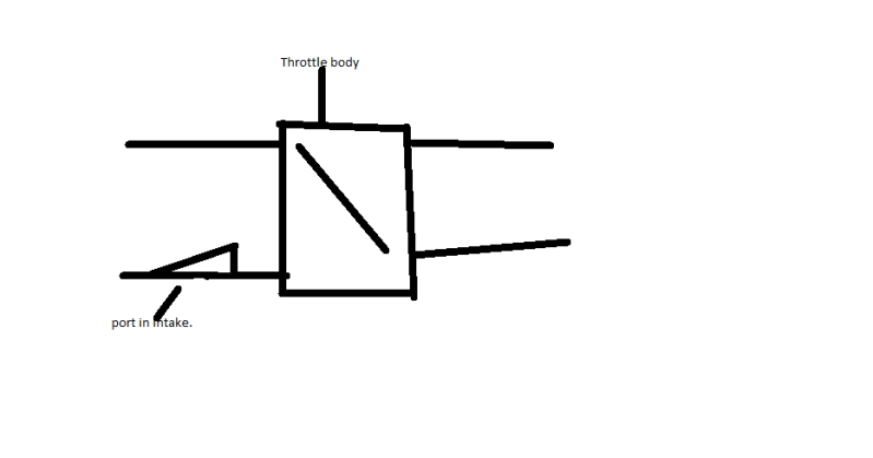
think im not getting what im trying to say across so ill draw a picture, for it to work the way the fsm describes. in order for the system to work it would have to have a port AFTER the throttle body but very close to the throttle plate to capture the high speed air before it slows down again...
in this pic the only place with high speed or high pressure air is right at the throttle plate, since air has pretty much no weight once you get about a inch(or mayby even less) away from the throttle plate your not going to have any venturi effect anymore. the port on the oem tube is just too far away its going to see the same vacuum and air speed as inside the intake.
The N/A system uses that port to supply air to the crank system, not to *push* air into the crank system.The plenum on the other end of the PCV system is supplying all the vacuum, it pulls air through the crank that was originally sourced at the intake tubing inlet.
as for the oil filter no its a issue ive have both on island and back home in ohio, first time i experienced it was first oil change, went and bought the stuff using the book at advance and sure enough didnt fit, thats how i first found out there computer said bosch dint have one and i was suprised you had one on your car. ive had the same problem at autozone, oreilys and napa. in fact i had this problem the other day getting oil filters for break in, books listed the wrong oil filter(way to big and wrong threads.) im suprised though because oreilys owns auto zone haha.
Did you disconnect the plenum to PCV valve connection/unseal it? that would stop the natural direction of there being little/no pressure at the drivers side port.
the point of the pic was to show what would work that port in that pic would have to go to the driver side valve cover, but our cars dont have anything like that its just a hole in a equal sized tube. with the pressure from the driver side port i had both the pcv valve and the driver side port unhooked from the intake and generated pressure. all engines will have a little blow by as well as turbulence from the parts moving which has to exit, anything attempting to enter the driver side port has to overcome that the point i was making is a little tube in the intake tube isnt going to do that, it has to have a greater force to push in there. i get what your saying and it sorta makes sense if the engine where a solid tube with no other factors affecting pressure and vacuum. but since there is pressure being built inside the engine its not enough to escape from the pcv valve alone its going to come out the driver port as well as shown on my engine before i even boosted it. engine did have 100k miles on it but had 150-153 across all cylinders on compression test so wasnt that bad.
Last edited by jerryd87; May 31, 2012 at 09:46 PM.
Thread Starter
New Member
iTrader: (2)
Joined: Sep 2011
Posts: 1,751
Likes: 7
From: Oregon from England
Yup, i understood the pic and your description, and as i said, i agree, your solution would cause a pressure point and the current setup won't.
If you had the PCV side of the setup disconnected, you'll feel 'pressure' from both sides, caused by blow-by and windage, that's normal and expected, i agree there too.
I also agree about the drivers side air flow having to over come that pressure in order for air from the intake tube to flow from tube to drivers side cover.
The engine kind of is the 'solid tube' but what you're not factoring in, is how the system is 'supposed to work' - it does not rely on the engine doing anything as far as pushing air out of itself.
If you like, you can actually 'start' the PCV system, at the passenger side connection to the plenum, it can make more sense if you start there.
The plenum is under constant vacuum whilst the engine is running, so any pipe connected to it generates quite a vacuum. So the PCV valve pipe, that comes from the plenum to the PCV valve, is sucking, strongly.
From that point, it's sucking more than the engine is generating via blow-by, so it has to get it's air from somewhere, it's a sealed vacuum connection, it can't suck nothing.
Hence the connection from the other side (drivers side) of the engine that latches to the filtered air from the intake tube. That intake tube connection is only there to allow air to be sucked in, not pushed in.
As for your compression,they were even, so good stuff But they're on the low side, lower limit is 142PSI.
If you had the PCV side of the setup disconnected, you'll feel 'pressure' from both sides, caused by blow-by and windage, that's normal and expected, i agree there too.
I also agree about the drivers side air flow having to over come that pressure in order for air from the intake tube to flow from tube to drivers side cover.
The engine kind of is the 'solid tube' but what you're not factoring in, is how the system is 'supposed to work' - it does not rely on the engine doing anything as far as pushing air out of itself.
If you like, you can actually 'start' the PCV system, at the passenger side connection to the plenum, it can make more sense if you start there.
The plenum is under constant vacuum whilst the engine is running, so any pipe connected to it generates quite a vacuum. So the PCV valve pipe, that comes from the plenum to the PCV valve, is sucking, strongly.
From that point, it's sucking more than the engine is generating via blow-by, so it has to get it's air from somewhere, it's a sealed vacuum connection, it can't suck nothing.
Hence the connection from the other side (drivers side) of the engine that latches to the filtered air from the intake tube. That intake tube connection is only there to allow air to be sucked in, not pushed in.
As for your compression,they were even, so good stuff
But they're on the low side, lower limit is 142PSI.

Wow something relatively simple has so many people confused including myself in some areas. Have seen soooooo many configurations and explanations with arguments on both sides till I just gave up. Can some of you who clearly understand confirm my setup.
Prior to FI I had the can routed inline from the PCV to front manifold port with no breather on the can, now (FI) I have the front intake port capped and routed the can w/breather from the PCV to the intake port along with the drivers side.
Just to add I have not drilled out my PCV valve.
Prior to FI I had the can routed inline from the PCV to front manifold port with no breather on the can, now (FI) I have the front intake port capped and routed the can w/breather from the PCV to the intake port along with the drivers side.
Just to add I have not drilled out my PCV valve.
Last edited by Sleeper_Z; Jun 1, 2012 at 08:50 PM.
Thread Starter
New Member
iTrader: (2)
Joined: Sep 2011
Posts: 1,751
Likes: 7
From: Oregon from England
I'm not certain on the FI setups, as i've never looked/thought into it hard enough as i don't have FI.
However, i've seen turbo setup suggestions of, same as normal, but add a can to the intake tube side as well.
Any venting to atmosphere generally doesn't help anything so far as clearing out the crank.
However, i've seen turbo setup suggestions of, same as normal, but add a can to the intake tube side as well.
Any venting to atmosphere generally doesn't help anything so far as clearing out the crank.
Wow something relatively simple has so many people confused including myself in some areas. Have seen soooooo many configurations and explanations with arguments on both sides till I just gave up. Can some of you who clearly understand confirm my setup.
Prior to FI I had the can routed inline from the PCV to front manifold port with no breather on the can, now (FI) I have the front intake port capped and routed the can w/breather from the PCV to the intake port along with the drivers side.
Just to add I have not drilled out my PCV valve.
Prior to FI I had the can routed inline from the PCV to front manifold port with no breather on the can, now (FI) I have the front intake port capped and routed the can w/breather from the PCV to the intake port along with the drivers side.
Just to add I have not drilled out my PCV valve.
when you get in depth into the engineering of vehicles there is nothing really simple, everything matters and taking everything into account is what separates the successful build from the disasters. its always the stuff that seems simple that ends up being the problem.
theres really no purpose to have air going into the crankcase it does nothing but hurt performance from extra turbulence inside the crankcase. im not sure why any system could possibly want air going in.
Last edited by jerryd87; Jun 1, 2012 at 09:08 PM.
^Very true, but meant simple in the way of being able to config/route the system.
No pics at the moment as I have yet to finalize a verified way of routing my system.
Simply put:
PCV > Breather Can >Intake tube - Driver side directly to Intake tube. This is the way I planned to route it. Also capping the front intake port where the original hose went into the pcv valve.
No pics at the moment as I have yet to finalize a verified way of routing my system.
Simply put:
PCV > Breather Can >Intake tube - Driver side directly to Intake tube. This is the way I planned to route it. Also capping the front intake port where the original hose went into the pcv valve.
a third option is to get one of the exhuast setups that dumps the breather port into the exhuast. i would say go that route or breather, trying to send the air back into the intake on fi is really sub par at best.
Thread Starter
New Member
iTrader: (2)
Joined: Sep 2011
Posts: 1,751
Likes: 7
From: Oregon from England

The *whole* reason you want air going into the crank is to clear out the corrosive gasses generated in there, which are really bad mmkay.
Thread Starter
New Member
iTrader: (2)
Joined: Sep 2011
Posts: 1,751
Likes: 7
From: Oregon from England
That's why you have a can on both sides. with the intake from each can fitted to the engine side.
FI will give you blowby from both ports, but ideally you want the air going back into the system again to take advantage of the vacuum from one side.
FI will give you blowby from both ports, but ideally you want the air going back into the system again to take advantage of the vacuum from one side.
ive seen major performance gains from eliminating windage and turbulance inside the crankcase, as much as 75 hp in extreme cases, thats why things like windage trays exist. what corrosive gases? outside of blowby which dosnt need air going to it, it will exit fine on its own through the intake manifold or breather whichever setup you have. the only thing in there that is able to generate and gas is oil, and its only going to generate that if it foaming or aeration as some say, which is going to fry th engine from air being in the oil not any corrosive gases.
what gases exactly are you talking about? because the only thing in the engine that will corrode the engine is coolant which shouldnt be in anywhere but the coolant passages which dont see any part of the pcv system. think we are starting to get into old wives tales now(well mechanic version.) because if there where corrosive gases every race engine and numerous street vehicles would have problems, which even with google i cannot find any issues with engine corroding from "corrosive gases" inside the crank case.
what gases exactly are you talking about? because the only thing in the engine that will corrode the engine is coolant which shouldnt be in anywhere but the coolant passages which dont see any part of the pcv system. think we are starting to get into old wives tales now(well mechanic version.) because if there where corrosive gases every race engine and numerous street vehicles would have problems, which even with google i cannot find any issues with engine corroding from "corrosive gases" inside the crank case.