
Interior LED Conversion


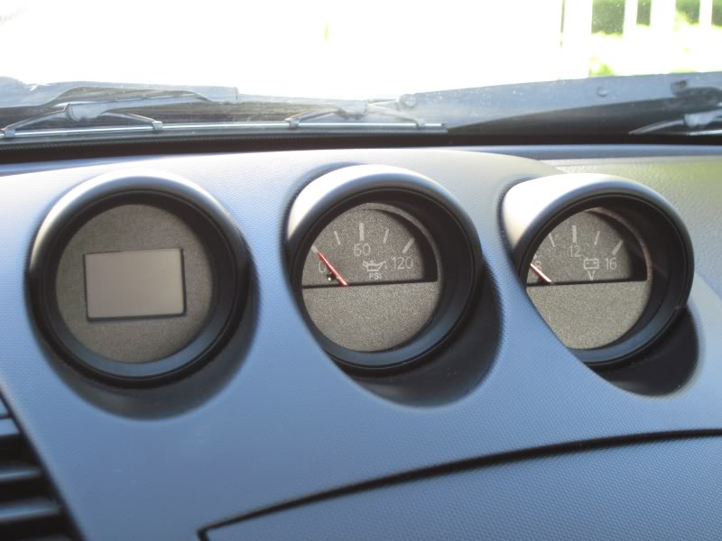
I hit up blackcatcustom.com for new inserts for the center console triple gauge cluster that would get rid of the amber characters and make the surface match the texture of the new gauge faces.
These are the first set and they are working out the adhesive still. I expect (and will suggest) that they include these as a standard part of their 350Z gauge faces kit, with or without the lettering.
The funky coloring on the arch of the right most gauge is a result of me messing around with a sharpie. The very top edge of the arch had a light colored edge and I was trying to mask it.
When they send me the final set that has the adhesive, I will replace.
Last edited by lbz; Nov 15, 2009 at 02:34 PM.


I hit up blackcatcustom.com for new inserts for the center console triple gauge cluster that would get rid of the amber characters and make the surface match the texture of the new gauge faces.
These are the first set and they are working out the adhesive still. I expect (and will suggest) that they include these as a standard part of their 350Z gauge faces kit, with or without the lettering.
The funky coloring on the arch of the right most gauge is a result of me messing around with a sharpie. The very top edge of the arch had a light colored edge and I was trying to mask it.
When they send me the final set that has the adhesive, I will replace.
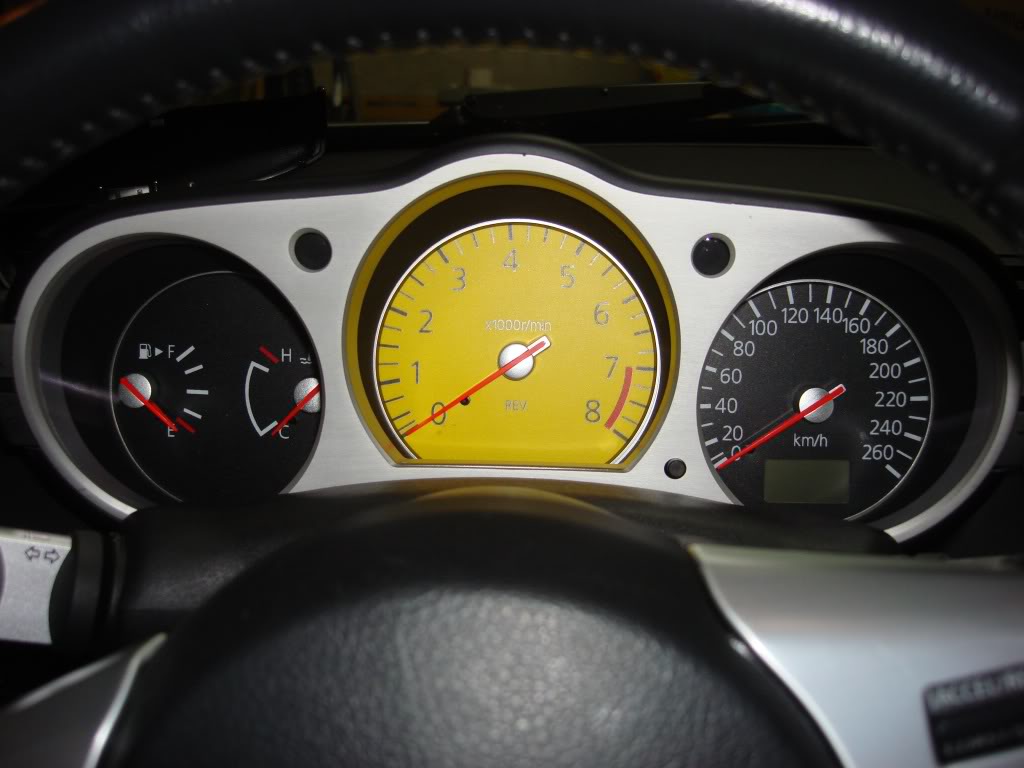
Also my boy who I do LED work with around his messed around with some needles from another car and is like 50% done converting his needles to white.
^ that's a dam good idea, wish I would have thought of it! I've got a used cluster coming in tomorrow, will do it and post the results as an update to that section of the procedure.
If you can, would be cool to see the results of white needle conversion and to know which model car's needles work.
If you can, would be cool to see the results of white needle conversion and to know which model car's needles work.
But then again, on the one hand, the orange face would only be visible during the day and on the other, the red for the markings would only show up at night unless you had blackcatcustom lay in a red backing.
A neutral backing would show white-ish for the markings during the day as the circuit board housing is white plastic. Of course you could paint it red...
I guess the simplest way would be orange face with a red backing and change the LEDs to red.
Needles are amber... might be not be as visible during the day against the orange face, unless, you painted them black but then they would not light up at night...

^ that's a dam good idea, wish I would have thought of it! I've got a used cluster coming in tomorrow, will do it and post the results as an update to that section of the procedure.
If you can, would be cool to see the results of white needle conversion and to know which model car's needles work.
If you can, would be cool to see the results of white needle conversion and to know which model car's needles work.
Played with resistors for the door controls with mixed results.
Driver's side - definitely better on both the window and the lock switch with the lock switch standing out compared to the window switches.
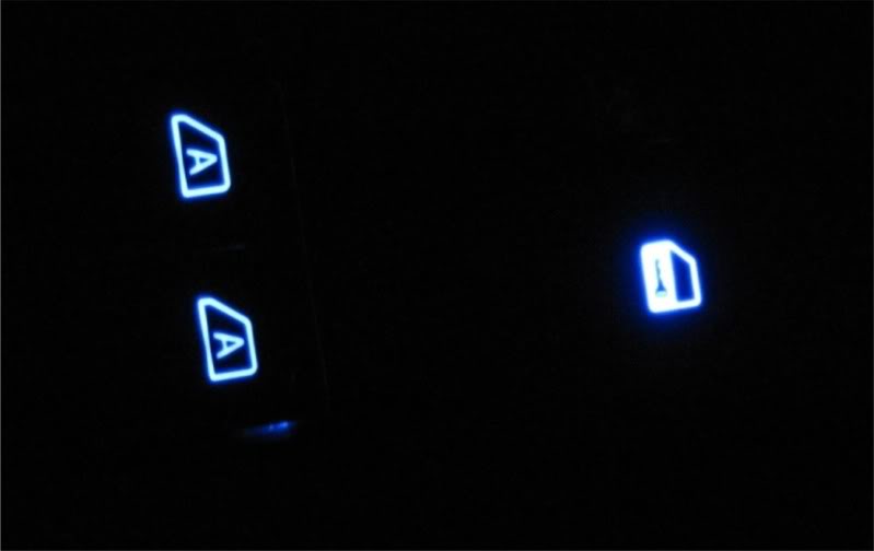
Passenger side - good improvement on the lock switch but the window switch did not improve as much as the drivers side. They look the same here but to my naked eye, passenger side seemed just a bit dimmer.
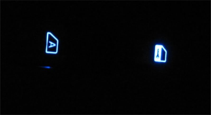
Resistors on the passenger side are totally different than on the driver side. Window resistor on passenger side is 100 ohm and I didn't have anything smaller so I soldered two 111's in parallel.
I'm not going to update the DIY sections until I cover the AC dial pointers for 03 - 05, the odometer LCD for polarity reversal and the silver buttons on the sides of the main cluster.
Driver's side - definitely better on both the window and the lock switch with the lock switch standing out compared to the window switches.
Passenger side - good improvement on the lock switch but the window switch did not improve as much as the drivers side. They look the same here but to my naked eye, passenger side seemed just a bit dimmer.
Resistors on the passenger side are totally different than on the driver side. Window resistor on passenger side is 100 ohm and I didn't have anything smaller so I soldered two 111's in parallel.
I'm not going to update the DIY sections until I cover the AC dial pointers for 03 - 05, the odometer LCD for polarity reversal and the silver buttons on the sides of the main cluster.
Last edited by lbz; Nov 21, 2009 at 10:23 PM.
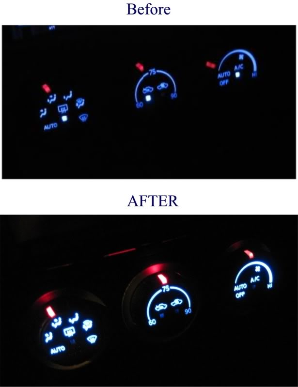
AC **** Pointers. Looking much better.
I didn't intend for the blue backlighting to be brighter but must be a result of changing out the ones for the pointers.
Pointers definitely improved.
I didn't intend for the blue backlighting to be brighter but must be a result of changing out the ones for the pointers.
Pointers definitely improved.
Took a look at the speedo / tach board tonight. Looks like more work than I want to get into though this weekend I may end up pulling resistors off a spare board just to see which LEDs turn off.
I swapped out the resistors for the buttons on the sides on the same spare board. Some improvement. No pics but will have them when I do my own board and can do a decent before / after comparison.
Aside from anything I might do with the speedo / tach board, I've got all the values and will update the first section that has the parts list this weekend.
Here's the details on the resistors.
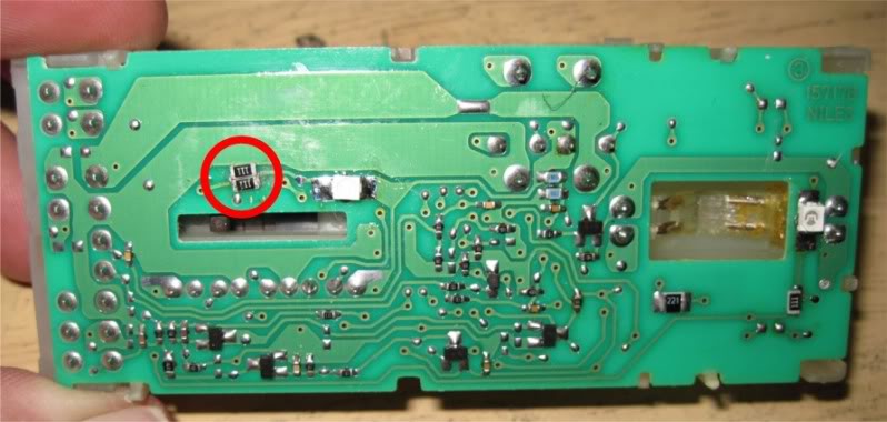
Door controls:
Replace the resistors pictured below.
Driver side: use resistor package type 2010, 100 ohms each
Passenger side: use resistor package type 1206, 56 ohms for both the window control and the lock switch. If you put two of the 110's in parallel with each other, that will work.
What I did was to put a blob of solder on the tip of the iron, hold the resistors together side by side with tweezers, tin one set of ends together and use that to line them up on the contacts. I then soldered the un-tinned ends in place first then went back and soldered in the tinned ends.
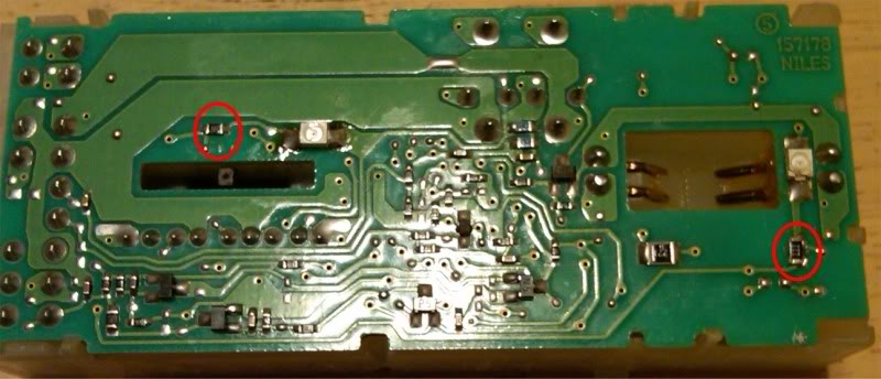
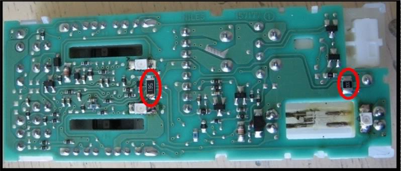
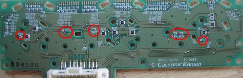
AC Controls (03 - 05 only)
Replace R825, R826, R828, R829, R831 and R832. These are all on the back side and are 911 ohms from the factory, not 116 like I first thought.
Use resistor package type 0805 100 ohms
This resulted in brighter **** pointers as well as brighter **** back lighting.
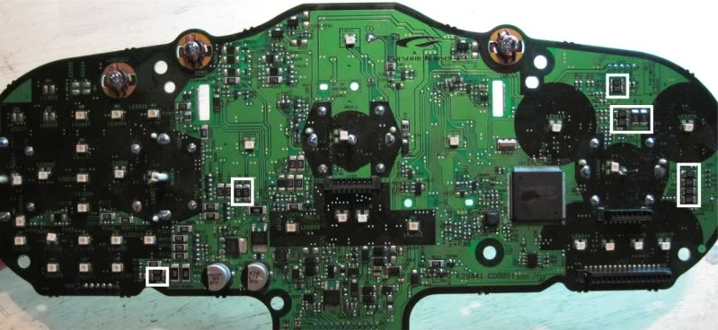
Speedo / Tach Cluster
Replace the resistors in white boxes below with 150 ohm, 2010 type surface mount. For the silver side buttons (upper right and lower left), I put two 221's in parallel which results in 110 ohms.
The pic below shows 221 ohm resistors because that's all I had on hand. I've ordered 150 ohm ones but won't get those in until next week. Will post before and after pics when I do mine.
This was all done on a test board that I have.
Anyone who has already done a conversion and wants a set of these resistors, PM me with a mailing address and I will send when I have the right values on hand and I've tested.
In the back of my mind I have a concern that maybe I'm over driving the LEDs which would result in a shorter lifespan. Acree mentioned something about going as low as 50 ohms on the door controls resulted in burned out LEDs but I've had mine in for a week or so, no problems yet though it's still early.
I see a nice difference, particularly in the AC controls.
I recommend you take pictures of the boards and save them before you change out resistors. This way you know the original values. Or you could use the pics in this DIY sections of this thread as the ones that show the components were taken before I switched them out.
Door controls:
Replace the resistors pictured below.
Driver side: use resistor package type 2010, 100 ohms each
Passenger side: use resistor package type 1206, 56 ohms for both the window control and the lock switch. If you put two of the 110's in parallel with each other, that will work.
What I did was to put a blob of solder on the tip of the iron, hold the resistors together side by side with tweezers, tin one set of ends together and use that to line them up on the contacts. I then soldered the un-tinned ends in place first then went back and soldered in the tinned ends.
AC Controls (03 - 05 only)
Replace R825, R826, R828, R829, R831 and R832. These are all on the back side and are 911 ohms from the factory, not 116 like I first thought.
Use resistor package type 0805 100 ohms
This resulted in brighter **** pointers as well as brighter **** back lighting.
Speedo / Tach Cluster
Replace the resistors in white boxes below with 150 ohm, 2010 type surface mount. For the silver side buttons (upper right and lower left), I put two 221's in parallel which results in 110 ohms.
The pic below shows 221 ohm resistors because that's all I had on hand. I've ordered 150 ohm ones but won't get those in until next week. Will post before and after pics when I do mine.
This was all done on a test board that I have.
Anyone who has already done a conversion and wants a set of these resistors, PM me with a mailing address and I will send when I have the right values on hand and I've tested.
In the back of my mind I have a concern that maybe I'm over driving the LEDs which would result in a shorter lifespan. Acree mentioned something about going as low as 50 ohms on the door controls resulted in burned out LEDs but I've had mine in for a week or so, no problems yet though it's still early.
I see a nice difference, particularly in the AC controls.
I recommend you take pictures of the boards and save them before you change out resistors. This way you know the original values. Or you could use the pics in this DIY sections of this thread as the ones that show the components were taken before I switched them out.
Last edited by lbz; Nov 26, 2009 at 08:25 PM.
Great! 
Do me a favor and keep an eye, when you can safely of course, on the red dial pointers as you move the dials. I want to make sure they stay lit as the dials move. When working on it, I had to go back once or twice to deal with them cutting out while moving.
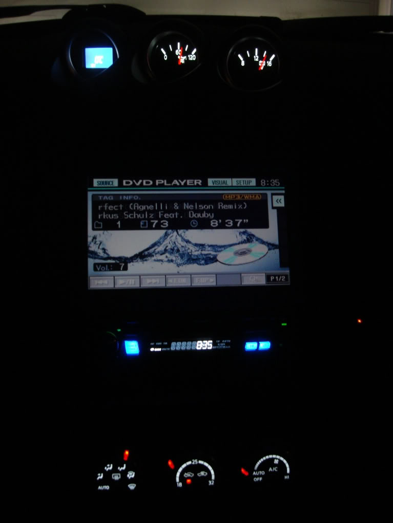
I'm definitely going to the next meeting. If you want, I can ship you a converted stock radio face plate. I've already got the LCD conversion done, just need to do the buttons back lighting. Sitting above the new AC controls, I think it would look sick. I'm thinking that back lighting the volume **** red with everything else blue would be a nice custom touch and would carry the blue with red accent theme up the console.
Not sure if you have time to do it but if you could pull the radio, swapping out the front face plate takes all of a couple minutes.
I've got details in the DIY for how to pull the radio, just need a #2 phillips screwdriver and 30 minutes or so to get it out, same going back in.
Do me a favor and keep an eye, when you can safely of course, on the red dial pointers as you move the dials. I want to make sure they stay lit as the dials move. When working on it, I had to go back once or twice to deal with them cutting out while moving.
I'm definitely going to the next meeting. If you want, I can ship you a converted stock radio face plate. I've already got the LCD conversion done, just need to do the buttons back lighting. Sitting above the new AC controls, I think it would look sick. I'm thinking that back lighting the volume **** red with everything else blue would be a nice custom touch and would carry the blue with red accent theme up the console.
Not sure if you have time to do it but if you could pull the radio, swapping out the front face plate takes all of a couple minutes.
I've got details in the DIY for how to pull the radio, just need a #2 phillips screwdriver and 30 minutes or so to get it out, same going back in.
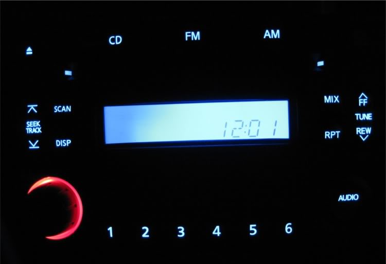
I just finished up the stock radio face plate and if I don't say so myself it looks nice.
The red around the volume **** is an idea I got from seeing someone else do their's that way.
Serf, I'm gonna ship this up to you tomorrow.
The red around the volume **** is an idea I got from seeing someone else do their's that way.
Serf, I'm gonna ship this up to you tomorrow.
Last edited by lbz; Nov 27, 2009 at 05:20 PM.

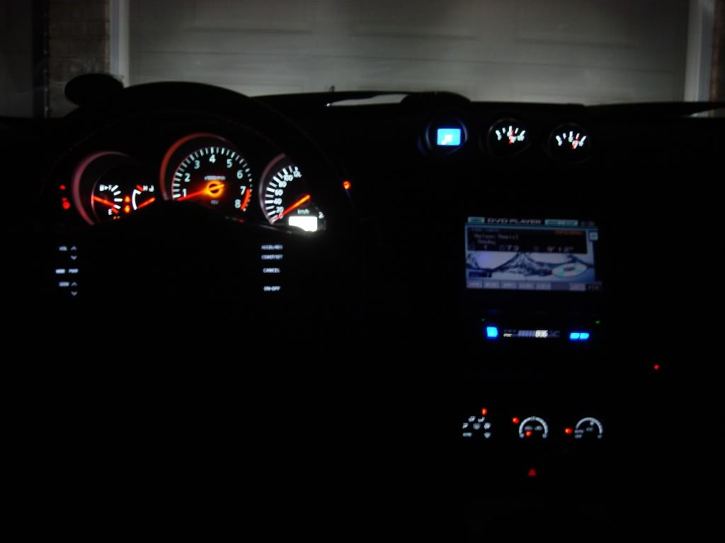
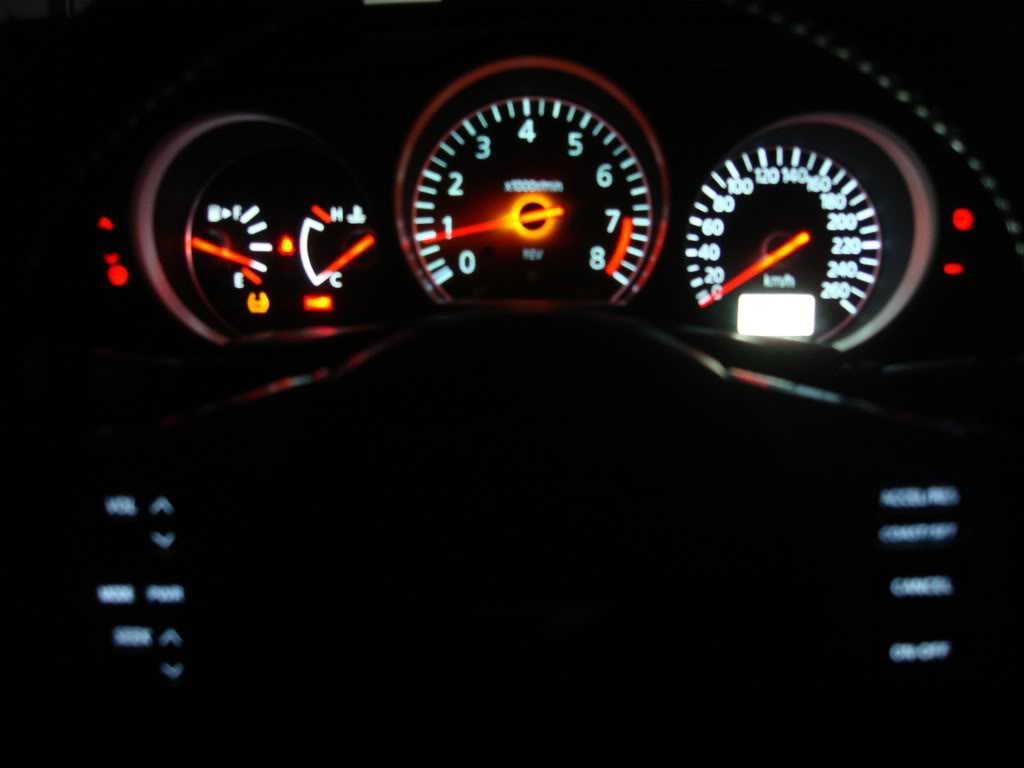
Hello everyone, here are some pictures of my LED conversion just went with Red and White scheme, looks much better in person. Big thanks goes out to lbz for all his help!
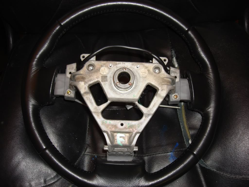
Heres the steps to the steering wheel LED conversion. First follow these instructions for removing the steering wheel.
https://my350z.com/forum/body-interi...t-install.html
Once you have the steering wheel of the car. Remove the two remaining screws holding the controls in place.
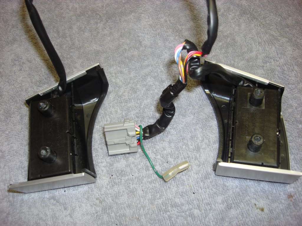
Working on one side at a time, remove the board by relessing the two clips.
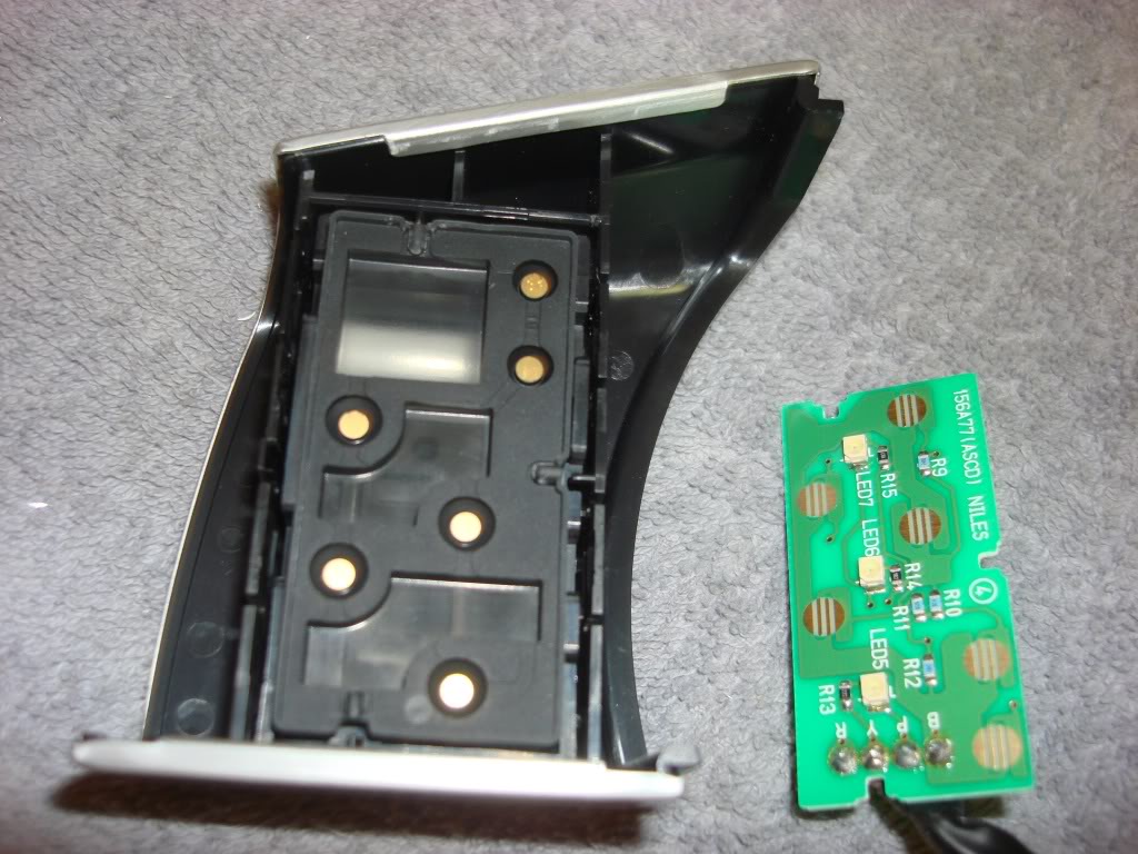
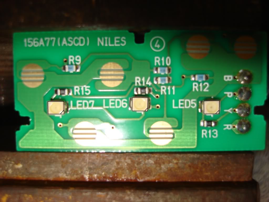
There are 3 PLCC2 LEDs to be changed. Notice their orientation outlined with black lines.
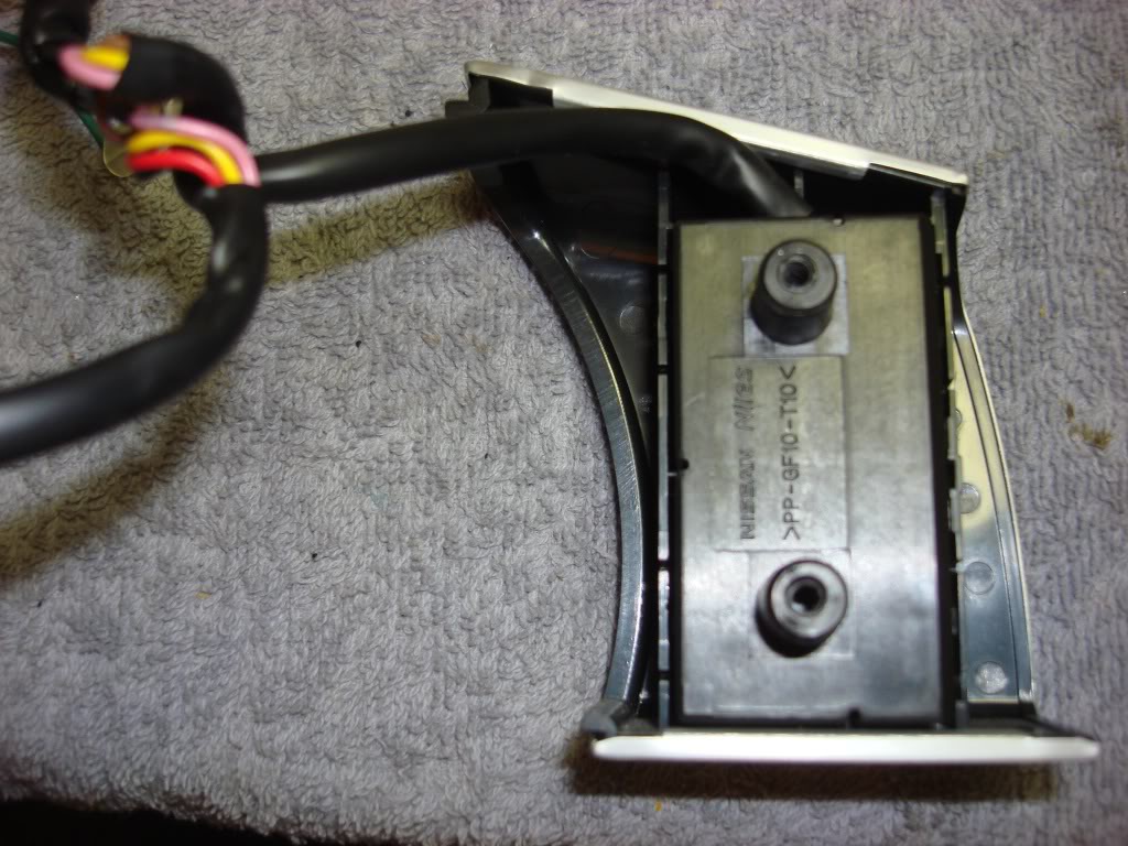
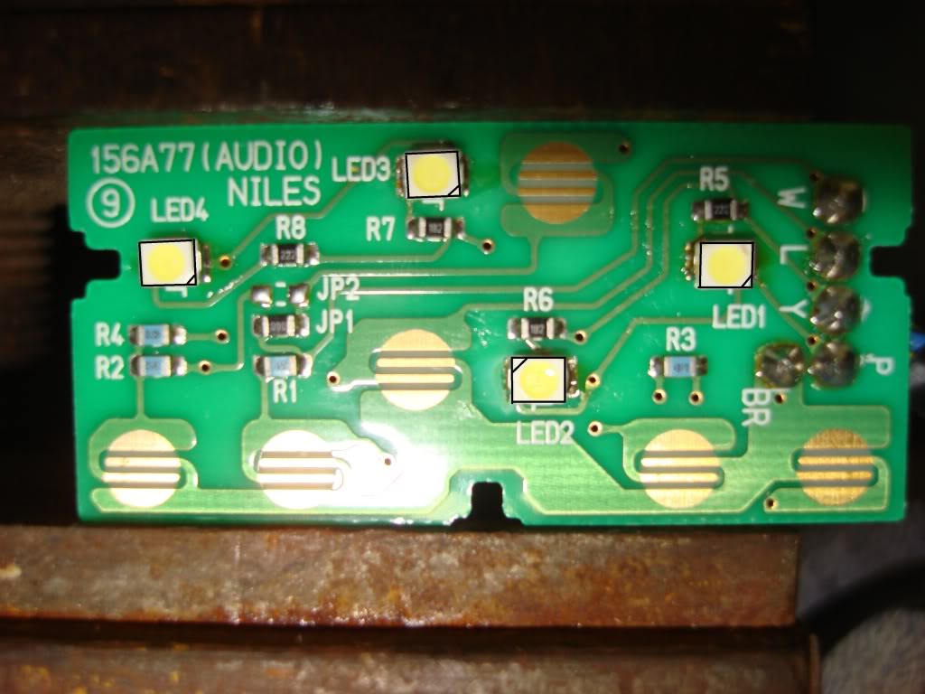
Take the board out of the radio controls
Here you have to change 4 PLCC2 LEDs again notice their orientation outlined with black lines.
That's all put everything back together.
Heres the steps to the steering wheel LED conversion. First follow these instructions for removing the steering wheel.
https://my350z.com/forum/body-interi...t-install.html
Once you have the steering wheel of the car. Remove the two remaining screws holding the controls in place.
Working on one side at a time, remove the board by relessing the two clips.
There are 3 PLCC2 LEDs to be changed. Notice their orientation outlined with black lines.
Take the board out of the radio controls
Here you have to change 4 PLCC2 LEDs again notice their orientation outlined with black lines.
That's all put everything back together.


I see a lot of guides that show people how to use PLCC-2 LEDs in place of the PLCC-4 type by soldering to only two of the PLCC-4 pads. This will allow the LED to work, but you're losing half of your heat sink. In general, Nissan went with PLCC-4 on lights that stay on constantly and PLCC-2 for lights that only come on temporarily (like the check engine light). So you'll notice 4 huge pads under each PLCC-4 LED to help suck the heat away from the LED so it will last longer.
This is just FYI, but I would recommend using the correct type if you want to extend your LED life. Using either type will function fine. If you're going with brighter LEDs than Nissan originally used then you'll likely get more heat so this could end up being more important.
This is just FYI, but I would recommend using the correct type if you want to extend your LED life. Using either type will function fine. If you're going with brighter LEDs than Nissan originally used then you'll likely get more heat so this could end up being more important.