
RevUp Vortech Installation - Joining the ranks of FI


Well, comes the time to tell the tale. Of the quest for power. Boosted power. The majesty of forced induction, of wailing supercharger gearing, and the siren song of squealing tires with rushing wind. (Bear with me as this is the first time I have posted a new thread of this length and complexity)
Okay, it's not Hemingway,��..but it was fun. What follows is a rather long, but precise, re-telling of our journey in the hopes that we can repay those who have posted before and, perhaps, add a little to that knowledgebase, for those who will surely follow.
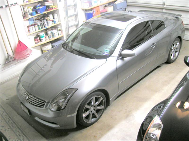
But first, the decision-making process that led us, inevitably, to supercharging a Z. We had rejected the thought of buying the new GT-R when it does become available. No, not because the styling is just a little off for our taste and not because the cost is a bit high (yes, we could afford it). But rather, we will no longer deal with the morons at the stealerships. We know the salespeople will be smelling blood and their behavior will be reprehensible (Pay attention, NISSAN people, oh wait; only the parts and service departments frequent these boards, oh well, mores� the pity, NISSAN). Sorry, NISSAN, get a new pack of sales-dogs and you might be able to sell up-market cars otherwise expect sales to be dismal and with little repeat business. No, the only path to truly awesome power lay along the way of 'DIY'. We decided to transform my husband's 2006 Grand Touring 350Z (my 2004 G35 Coupe is just fine, the way she is [yes, she, her name is 'Lucy' and she proudly carries the 'Lady Jax' title]).
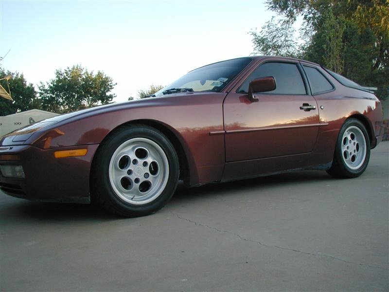
Now, we did weigh the pros and cons of turbocharging. Having owned and rebuilt a 1986 Porsche 944T (951), we were fairly familiar with the intricacies involved. As sweet as that car was (yes, she was a 'she', her name was Queen, as in 'whatever the Queen wants, the Queen gets......', you know that story, I am sure).
We looked at the various kits available and their solutions to the problems of power, heat and reliability. Without going to the trouble of strengthening the engine and significantly upgrading the cooling, fuel and drivetrain there was not a suitable level of reliability. Sure, there would be plenty of power and torque but it would necessitate a level of complication that was unacceptable to us. Better to leave this to the courageous souls sturdy enough to withstand the rigors of exhaust-driven impellers.
That eliminated half the field. Next came the essential research of these forums and on G35driver.com and *********.com. Several weeks were spent during the spring poring over seemingly endless threads and articles of accumulated knowledge. Initially, we thought the HKS supercharger system would offer the best mix of reliability and a complete kit for ease of construction. Without a good local tuner and dynamometer we wanted the most straight-forward approach possible. Alas, the HKS, though listed at numerous websites, was not to be found anywhere throughout the land. There were hints that a new kit would be available in the fall, September maybe, but no one knew for sure. Our quest continued.
The remaining contestants boiled down to only two realistic choices, ATI or Vortech. Both have their good points and their weak points. Both have specific requirements in construction and maintenance. Each has unique characteristics of power and torque. Long we dwelled on the problem of which was better, lost in the land of TMI (too much information).
(Bear with me as this is the first time I have posted a new thread of this length and complexity) Okay, it's not Hemingway,��..but it was fun. What follows is a rather long, but precise, re-telling of our journey in the hopes that we can repay those who have posted before and, perhaps, add a little to that knowledgebase, for those who will surely follow.
But first, the decision-making process that led us, inevitably, to supercharging a Z. We had rejected the thought of buying the new GT-R when it does become available. No, not because the styling is just a little off for our taste and not because the cost is a bit high (yes, we could afford it). But rather, we will no longer deal with the morons at the stealerships. We know the salespeople will be smelling blood and their behavior will be reprehensible (Pay attention, NISSAN people, oh wait; only the parts and service departments frequent these boards, oh well, mores� the pity, NISSAN). Sorry, NISSAN, get a new pack of sales-dogs and you might be able to sell up-market cars otherwise expect sales to be dismal and with little repeat business. No, the only path to truly awesome power lay along the way of 'DIY'. We decided to transform my husband's 2006 Grand Touring 350Z (my 2004 G35 Coupe is just fine, the way she is [yes, she, her name is 'Lucy' and she proudly carries the 'Lady Jax' title]).
Now, we did weigh the pros and cons of turbocharging. Having owned and rebuilt a 1986 Porsche 944T (951), we were fairly familiar with the intricacies involved. As sweet as that car was (yes, she was a 'she', her name was Queen, as in 'whatever the Queen wants, the Queen gets......', you know that story, I am sure).
We looked at the various kits available and their solutions to the problems of power, heat and reliability. Without going to the trouble of strengthening the engine and significantly upgrading the cooling, fuel and drivetrain there was not a suitable level of reliability. Sure, there would be plenty of power and torque but it would necessitate a level of complication that was unacceptable to us. Better to leave this to the courageous souls sturdy enough to withstand the rigors of exhaust-driven impellers.
That eliminated half the field. Next came the essential research of these forums and on G35driver.com and *********.com. Several weeks were spent during the spring poring over seemingly endless threads and articles of accumulated knowledge. Initially, we thought the HKS supercharger system would offer the best mix of reliability and a complete kit for ease of construction. Without a good local tuner and dynamometer we wanted the most straight-forward approach possible. Alas, the HKS, though listed at numerous websites, was not to be found anywhere throughout the land. There were hints that a new kit would be available in the fall, September maybe, but no one knew for sure. Our quest continued.
The remaining contestants boiled down to only two realistic choices, ATI or Vortech. Both have their good points and their weak points. Both have specific requirements in construction and maintenance. Each has unique characteristics of power and torque. Long we dwelled on the problem of which was better, lost in the land of TMI (too much information).
Then, as fate would have it, along comes Jeremy Tibbs and his �summer group buy� on Vortech superchargers. Enuf� said. We promptly joined up and placed an order for a Tuner Kit (the only type available for the RevUp 350Z�s, for some arcane reason). Jeremy also provided additional price incentives for the remaining equipment to complete the installation. All told, we purchased the Vortech, the Turbo XS UTEC with a MAP sensor, an Innovate xD-16 AFR gauge and LC-1 oxygen sensor kit, a CJ Motorsports fuel return system (Stage 2 with the hard-pipe) and the Walboro fuel pump, all from Mr. Tibbs in Orlando. Despite having a very hectic summer and taking a seminar in L.A., Mr. Tibbs delivered the goods in a timely fashion to our humble little garage. He was also an invaluable source of information on how to re-make an ordinary sportscar into a daily-driven supercar.
Now along the way, we did need to do a few renovations to our work-site in the way of additional tools for working with AN fittings and stainless steel hoses, a bench grinder, additional work-tables, etc. While none of this is essential for installing the Vortech, we chose to use this opportunity to acquire a few more toys (for, as you know, he who dies with the most toys���..).
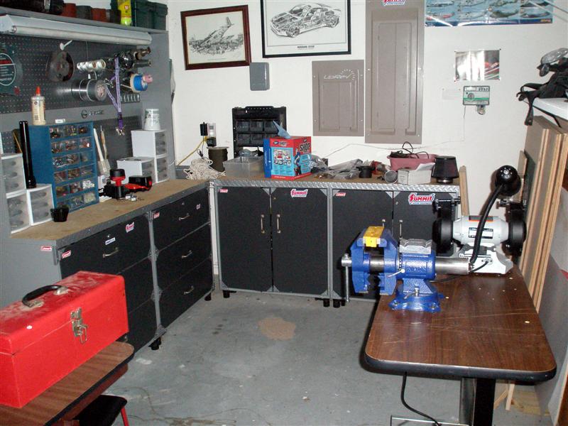
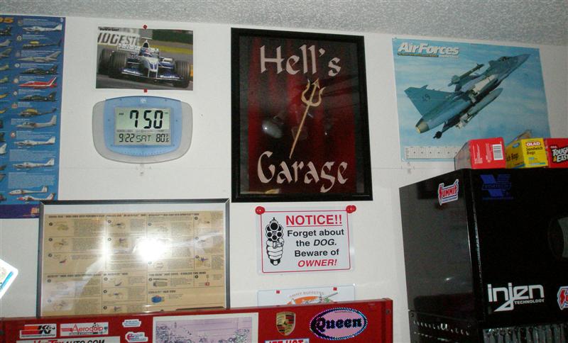
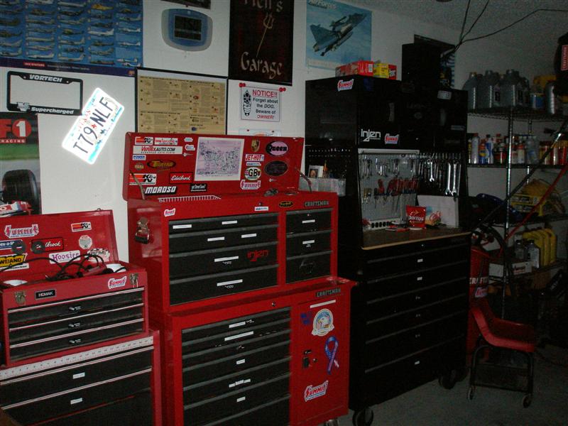
Given the transformation of our garage and the overwhelming heat in our part of the country, we christened our automotive den �Hell�s Garage� (with credit to Gordon Ramsay and his show��.�Get away from that grinder, you DONKEY!!!!�).
We were now ready to begin.
We divided the tasks to be done into stages that would be more readily accomplished together and tested prior to proceeding to the next step. Not needing the car on a daily basis allowed us to go at a more leisurely pace between working shifts. We delineated upgrades first to the exhaust system, then to the fuel system, then to the electronics and, finally, the supercharger, itself.
Now along the way, we did need to do a few renovations to our work-site in the way of additional tools for working with AN fittings and stainless steel hoses, a bench grinder, additional work-tables, etc. While none of this is essential for installing the Vortech, we chose to use this opportunity to acquire a few more toys (for, as you know, he who dies with the most toys���..).
Given the transformation of our garage and the overwhelming heat in our part of the country, we christened our automotive den �Hell�s Garage� (with credit to Gordon Ramsay and his show��.�Get away from that grinder, you DONKEY!!!!�).
We were now ready to begin.
We divided the tasks to be done into stages that would be more readily accomplished together and tested prior to proceeding to the next step. Not needing the car on a daily basis allowed us to go at a more leisurely pace between working shifts. We delineated upgrades first to the exhaust system, then to the fuel system, then to the electronics and, finally, the supercharger, itself.
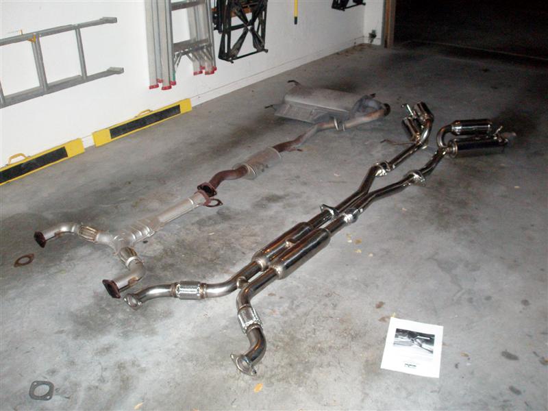
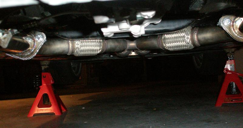
The exhaust system was the first, and the easiest modification, we performed. We installed an HKS Hi-Performance Titanium-Tip exhaust. This is a true-dual system that provides 2.5 inch pipes from each catalytic convertor to the rear of the car. This gave a very nice �rumble� to the exhaust note without being too loud.
After testing this installation and being happy with the fit and sound we then turned to the �cats� themselves.
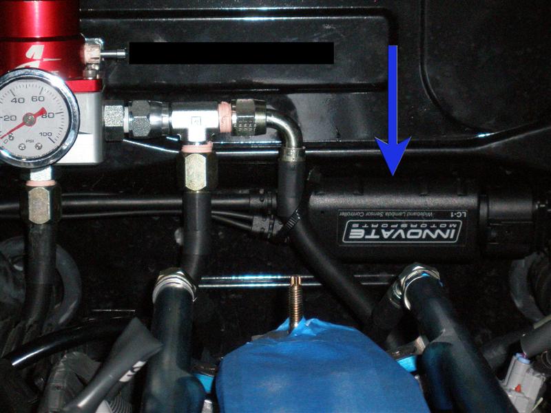
We looked at all of the alternatives and decided that we wanted convertors with a metallic matrix and a 2.5 inch pipe of stainless steel. The best one meeting those requirements appeared to be the Altered Atmosphere Hi-Flow �cats�. We had a stainless steel bung welded to the driver�s side cat (on Jeremy�s advice) ahead of the convertor element and installed the Innovate LC-1 oxygen sensor in this spot. This would prove invaluable later during the tuning process and while driving the car. We were very careful to find a welding shop that could do �MIG� stainless steel welding so as not to have any premature corrosion (I know how you guys hate premature corrosion) at a site well-hidden in the engine bay. We ran the wires up to the factory oxygen sensor above it (zip-tying the wires together and away from the exhaust) and attached the LC-1 unit, itself, to the firewall, just behind the engine. Innovate has thoughtfully provided enough additional wire to place the LC-1 at just this spot.
This then allowed us to run the wires over to the battery �box� for easy entry into the passenger compartment through the rubber membranes on the engine side and the passenger side of the battery �box�.
We tested the entire assembly and fixed a couple of small leaks at the joints by using double gaskets, heat-wrap (between the gaskets and NOT around a leak) and silver anti-seize compound. A careful application of torque on the joining bolts snugged everything up, nicely.
After testing this installation and being happy with the fit and sound we then turned to the �cats� themselves.
We looked at all of the alternatives and decided that we wanted convertors with a metallic matrix and a 2.5 inch pipe of stainless steel. The best one meeting those requirements appeared to be the Altered Atmosphere Hi-Flow �cats�. We had a stainless steel bung welded to the driver�s side cat (on Jeremy�s advice) ahead of the convertor element and installed the Innovate LC-1 oxygen sensor in this spot. This would prove invaluable later during the tuning process and while driving the car. We were very careful to find a welding shop that could do �MIG� stainless steel welding so as not to have any premature corrosion (I know how you guys hate premature corrosion) at a site well-hidden in the engine bay. We ran the wires up to the factory oxygen sensor above it (zip-tying the wires together and away from the exhaust) and attached the LC-1 unit, itself, to the firewall, just behind the engine. Innovate has thoughtfully provided enough additional wire to place the LC-1 at just this spot.
This then allowed us to run the wires over to the battery �box� for easy entry into the passenger compartment through the rubber membranes on the engine side and the passenger side of the battery �box�.
We tested the entire assembly and fixed a couple of small leaks at the joints by using double gaskets, heat-wrap (between the gaskets and NOT around a leak) and silver anti-seize compound. A careful application of torque on the joining bolts snugged everything up, nicely.
We now turned our attention to the fuel system.
The fuel system required a partial disassembly of the interior of the car, so as not to spill fuel everywhere and to have plenty of room to work. We removed the seats, the dash-panels and the rear storage compartments. Next the tank canister was carefully removed. The Walboro fuel pump was installed in the canister and it was further modified for the fuel return system, per CJ Motorsports instructions. The only complication was that the Walboro is a bit bigger than the stock unit. The small tabs on the end of the pump needed to be clipped off to allow it to fit. We also decided to trim the rubber bumper and re-install it to minimize any noise from the pump. Doing this required that the tabs holding the pump in place be trimmed at the site of the canister�s hold-downs to allow the additional space for the rubber bumper to be in place. It sounds complicated but it is really very obvious once you have the parts in front of you. There are three �windows� that the hold-downs click into when the pump is assembled into the canister and we just carefully lengthened the �windows� with an Xacto knife (my hubbie uses a scalpel on a regular basis, so he got to do the whittling). Then the whole thing goes back together with the new pieces and hoses from the CJM kit and slides back down into the tank. Fini (sorry, we did not think to take pictures before we returned the unit to the tank, so you will just have to re-read the above paragraph carefully and picture it in your mind. Come on now, you can do it, young Jedi).
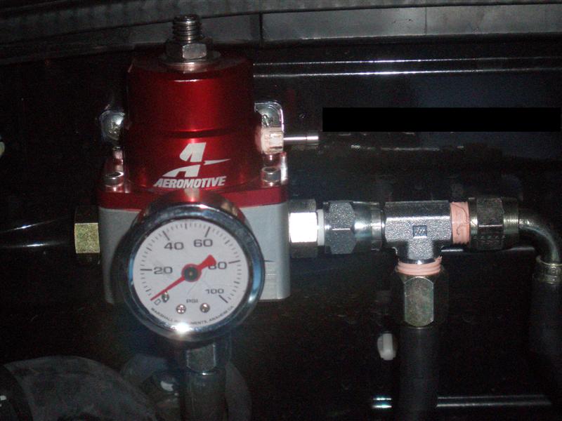
Next, the treacherous fuel lines. Having to install both the return line and the new hard-pipe we removed the factory hard-pipe from the tank all the way to the fuel damper on the back of the engine. Mind you, the CJM instructions give no real clue as to the installation of the lines, adapters, etc. Instead, we relied on my husband�s extensive experience in all things automotive (well, okay, he is at least still competent after being out of the field for several years and he can think on his feet��in a crunch). We laid the entire system out and compared it to the pictures on the website and suddenly it all made sense. We �snaked� the lines (both the short line for the hard-pipe and the longer line for the return system) through the very narrow opening between the front of the fuel tank and the bodywork. By using a nylon cord tied to the lines and me forcing the lines around the bend of the fuel tank and my husband using a set of MacGill forceps (don�t ask��..but you could use a LONG set of needle-nose pliers or by fiddling with a long/skinny flat-blade screwdriver) we managed to �convince� the lines to wend around the fuel tank and poke out from the bottom of the car. We then used the stock location for attaching the fuel lines next to the EVAP lines, modifying the plastic clips and zip-tying them together to run under the body and up to the passenger-side suspension point. We then attached the short flexible/shielded line to the hard-pipe. The fuel return line followed the EVAP lines into the engine bay and we removed the retaining clip that had held the original fuel line to the inside of the passenger wheel-well and used rubber-lined clamps to hold the fuel return line in place and away from the exhaust manifold. The shielded fuel line went under the catalytic convertor then up along the side of the transmission until it was behind the engine. With that sorted, we then attached the Y-adapter to the shielded line and attached the two lines that would connect to the fuel rails. The fuel return line wound up along the passenger wheel well and then over to the firewall where it was attached to the bottom of the Aeromotive fuel pressure regulator. We had attached this to the firewall on the last flat space on the passenger side (next to the battery box) with the top of it flush with the rubber weather-stripping. We used two sheet-metal screws to hold the regulator firmly in place and connected the return line to the bottom of the regulator. By placing the regulator here it allowed us to attach the pressure gauge to the front of the regulator, clear the stock plenum and still see the gauge when the engine was running.
Whew��what a long day that was.
Having said that, I feel that a word about precision is in order. During this entire procedure we Teflon-taped every joint and torqued each carefully in place. In spite of this, my husband still managed to miss one joint at the fuel tank and we did get a little spillage later, during testing. So, take your time, double-check and triple-check your work and always, ALWAYS, test fuel system connections before �buttoning� everything up. It will definitely pay off in the end and the last thing you need is a hidden fuel leak burning up your precious baby. Oh, and one other thing. That damn connection of the fuel return line to the canister AN fitting is a ***** for clearance. I recommend that you coil one loop of the fuel return line around the canister (yes, there is plenty of extra�..thanks, Charles) and then connect it with the line AN fixture lying flat against the tank. Done, finally���
�STEP AWAY FROM THE CAR, MA�AM, AND PUT YOUR TOOLS ON THE GROUND!!!� said the automotive-sanity police officer through his megaphone at a safe distance from the garage. ���.We took a few days off (to go to work) and then resumed later in the week.
The fuel system required a partial disassembly of the interior of the car, so as not to spill fuel everywhere and to have plenty of room to work. We removed the seats, the dash-panels and the rear storage compartments. Next the tank canister was carefully removed. The Walboro fuel pump was installed in the canister and it was further modified for the fuel return system, per CJ Motorsports instructions. The only complication was that the Walboro is a bit bigger than the stock unit. The small tabs on the end of the pump needed to be clipped off to allow it to fit. We also decided to trim the rubber bumper and re-install it to minimize any noise from the pump. Doing this required that the tabs holding the pump in place be trimmed at the site of the canister�s hold-downs to allow the additional space for the rubber bumper to be in place. It sounds complicated but it is really very obvious once you have the parts in front of you. There are three �windows� that the hold-downs click into when the pump is assembled into the canister and we just carefully lengthened the �windows� with an Xacto knife (my hubbie uses a scalpel on a regular basis, so he got to do the whittling). Then the whole thing goes back together with the new pieces and hoses from the CJM kit and slides back down into the tank. Fini (sorry, we did not think to take pictures before we returned the unit to the tank, so you will just have to re-read the above paragraph carefully and picture it in your mind. Come on now, you can do it, young Jedi).
Next, the treacherous fuel lines. Having to install both the return line and the new hard-pipe we removed the factory hard-pipe from the tank all the way to the fuel damper on the back of the engine. Mind you, the CJM instructions give no real clue as to the installation of the lines, adapters, etc. Instead, we relied on my husband�s extensive experience in all things automotive (well, okay, he is at least still competent after being out of the field for several years and he can think on his feet��in a crunch). We laid the entire system out and compared it to the pictures on the website and suddenly it all made sense. We �snaked� the lines (both the short line for the hard-pipe and the longer line for the return system) through the very narrow opening between the front of the fuel tank and the bodywork. By using a nylon cord tied to the lines and me forcing the lines around the bend of the fuel tank and my husband using a set of MacGill forceps (don�t ask��..but you could use a LONG set of needle-nose pliers or by fiddling with a long/skinny flat-blade screwdriver) we managed to �convince� the lines to wend around the fuel tank and poke out from the bottom of the car. We then used the stock location for attaching the fuel lines next to the EVAP lines, modifying the plastic clips and zip-tying them together to run under the body and up to the passenger-side suspension point. We then attached the short flexible/shielded line to the hard-pipe. The fuel return line followed the EVAP lines into the engine bay and we removed the retaining clip that had held the original fuel line to the inside of the passenger wheel-well and used rubber-lined clamps to hold the fuel return line in place and away from the exhaust manifold. The shielded fuel line went under the catalytic convertor then up along the side of the transmission until it was behind the engine. With that sorted, we then attached the Y-adapter to the shielded line and attached the two lines that would connect to the fuel rails. The fuel return line wound up along the passenger wheel well and then over to the firewall where it was attached to the bottom of the Aeromotive fuel pressure regulator. We had attached this to the firewall on the last flat space on the passenger side (next to the battery box) with the top of it flush with the rubber weather-stripping. We used two sheet-metal screws to hold the regulator firmly in place and connected the return line to the bottom of the regulator. By placing the regulator here it allowed us to attach the pressure gauge to the front of the regulator, clear the stock plenum and still see the gauge when the engine was running.
Whew��what a long day that was.
Having said that, I feel that a word about precision is in order. During this entire procedure we Teflon-taped every joint and torqued each carefully in place. In spite of this, my husband still managed to miss one joint at the fuel tank and we did get a little spillage later, during testing. So, take your time, double-check and triple-check your work and always, ALWAYS, test fuel system connections before �buttoning� everything up. It will definitely pay off in the end and the last thing you need is a hidden fuel leak burning up your precious baby. Oh, and one other thing. That damn connection of the fuel return line to the canister AN fitting is a ***** for clearance. I recommend that you coil one loop of the fuel return line around the canister (yes, there is plenty of extra�..thanks, Charles) and then connect it with the line AN fixture lying flat against the tank. Done, finally���
�STEP AWAY FROM THE CAR, MA�AM, AND PUT YOUR TOOLS ON THE GROUND!!!� said the automotive-sanity police officer through his megaphone at a safe distance from the garage. ���.We took a few days off (to go to work) and then resumed later in the week.
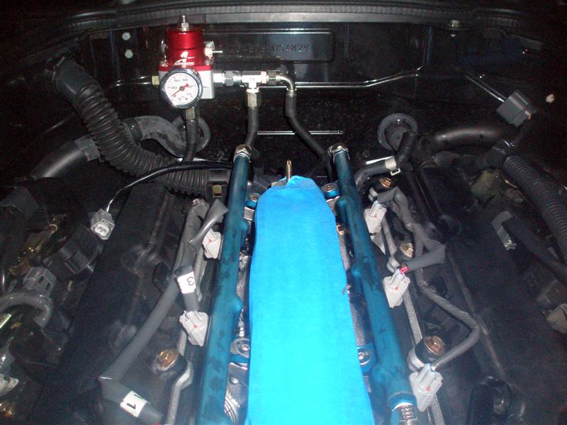
To provide better �breathing� for our Z (and not change the stock appearance too much) we had ordered the Motordyne MREV2 and 5/16� spacer for our car. In combination with the fuel rails from CJ Motorsports, we also added the Deatschwerks 550cc/min fuel injectors (thanks, again, Jeremy). So, we took everything from the top of the motor all the way down to the valve-covers and then built back up. We took this opportunity to change the spark plugs to Iridium units with a -6 rating (one step cooler). And while we had the wiring undone for the plugs and the injectors it was time to get the injectors, rails and lines in place. The Deatschwerks injectors are original equipment that have been modified for additional flow so you don�t need any special spacers. You can also send your original injectors back to Deatschwerks in Oklahoma for some reimbursement (check their website for the latest pay-back). What a deal, heh? The CJ Motorsports fuel rails are a piece of art with CNC milled pieces that fit �like a glove�.
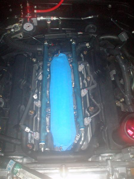
It�s a shame you can�t see them once you have the plenum on. So, again, there were no instructions on how to place the fuel lines but we could easily see that if you lay them down between the valve-covers and the injectors and below the wiring, they will exit at the back of the block and will hook right up to the regulator perfectly.
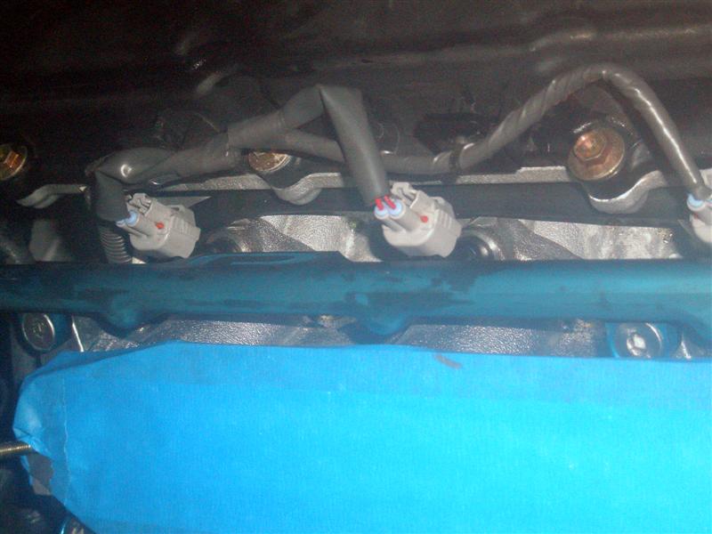
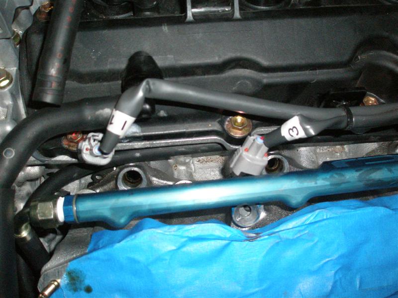
We cannot compliment Charles enough for the fit and finish of his fuel system. His instruction set, well���.Let us know if you need a little editing, we would be glad to help, Charles.
So, with all the lines laid, new sparkplugs installed, the injectors in place, and the rails attached, we then installed the MREV2, spacer and plenum top. We then hooked up the throttle body and MAF (shorty CAI-style) and proceeded to fire that �mother up to check the fuel lines and plenum for leaks. At this point, the aforementioned leak at the fuel tank presented itself but it was easily dealt with as we had not yet reinstalled the interior. The idle was rough, but we expected that as we had yet to hook up the UTEC and scale the injectors so we held the idle at about 1500rpm while we checked for leaks. Then shut it all down, disconnected the battery, took one step back and a deep sigh.
Now put your tools away, turn off the lights and go back into the house, young Jedi, for your journey has only just begun.
-Appropriate Interlude for Rest (and work)-
It�s a shame you can�t see them once you have the plenum on. So, again, there were no instructions on how to place the fuel lines but we could easily see that if you lay them down between the valve-covers and the injectors and below the wiring, they will exit at the back of the block and will hook right up to the regulator perfectly.
We cannot compliment Charles enough for the fit and finish of his fuel system. His instruction set, well���.Let us know if you need a little editing, we would be glad to help, Charles.
So, with all the lines laid, new sparkplugs installed, the injectors in place, and the rails attached, we then installed the MREV2, spacer and plenum top. We then hooked up the throttle body and MAF (shorty CAI-style) and proceeded to fire that �mother up to check the fuel lines and plenum for leaks. At this point, the aforementioned leak at the fuel tank presented itself but it was easily dealt with as we had not yet reinstalled the interior. The idle was rough, but we expected that as we had yet to hook up the UTEC and scale the injectors so we held the idle at about 1500rpm while we checked for leaks. Then shut it all down, disconnected the battery, took one step back and a deep sigh.
Now put your tools away, turn off the lights and go back into the house, young Jedi, for your journey has only just begun.
-Appropriate Interlude for Rest (and work)-
Now that the work week was over and we had a free day we headed back to the car to install the �plumbing from hell�. The Vortech instructions tell you to take everything off the front of the car, from under the car and the air intake system. It is best to over-do this as more of the bits you remove the easier the installation to come.
More on this later. For now, we removed the intake down to the throttle system. We already had an Injen CAI installed so this was fairly easy to do. We left the one-way valve installed from the hose that runs from the valve cover vent to the air filter and installed a longer piece of hose to the new (and smaller) air filter at the radiator support/intake hole. We routed this hose under the other plumbing/wires and on top of the air-conditioning compressor to give us enough clearance for the associated supercharger plumbing. Leaving a few extra inches of hose at this point is a good idea as you will find that it is easier to move this hose around the oil drain line and still attach it to the air filter if you can warp it in a gentle curve. We then installed pieces in the following order:

1. Large diameter blue hose connector to the throttle with two large clamps
2. Small bent aluminum pipe
3. Large diameter blue hose connector with two large clamps
4. Factory MAF sensor with the electrical connector pointed down (for clearance)
5. Aluminum pipe with the bolt flange on one end to attach to the MAF sensor pipe
6. Small diameter blue hose connector with two large clamps
7. Aluminum pipe with several flattened surfaces to allow it to fit between the air-conditioning compressor and various hoses (remember to zip-tie the flexible AC line to the sway-bar attachment location from underneath the car, otherwise it will rub against the compressor pulley and cause a leak)
If all of this sounds like it is crowded, you can bet it is.
You can just see the air filter hose (with the Injen valve) running under the intake plumbing. The AC flexible hard pipe took some gentle bending to give adequate clearance and two of the wiring looms needed to be relocated. Just follow the Vortech instructions; in this case they are fairly accurate. Be sure and press backwards against the down pipe and install it as far back as possible so it clears the jackshaft bolt later on.
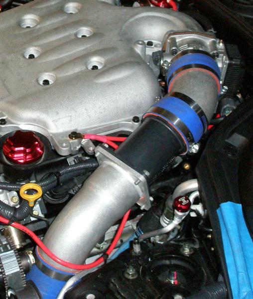
And, yes, this was on one of our numerous �trial fits� of the supercharger bracket, as you can see we DON�T have the gilmer belt on, yet. Regardless, you got about � inch clearance, at best, before that bolts eats its� way into the steel clamp! Again, more on that later.
It�s now time to move under the car.
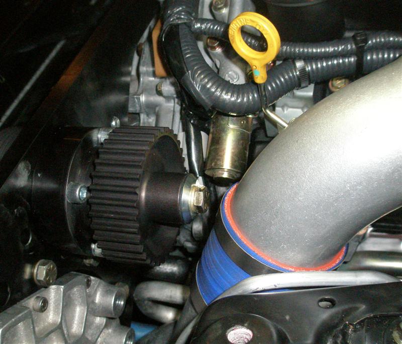
With the car on jack stands you will need to have it up as high as it can go in order to give you enough clearance to install the next bit of pipe (for those of you with NISMO sway-bars, you will find that you will need to �drop� the front bar down to give you some additional space). It is the really twisted bit of aluminum pipe with the straight run of pipe that runs along the bottom of the radiator. Which means you take the twisted end, put it between the two fans and �screw� it up and into position so that, eventually it will connect with the supercharger, itself. We taped it into position to continue installing all of the remaining plumbing. As you can see, it is a really tight fit.
But the pipe will fit without hitting any of the pulleys or belts��.just barely.
Next we installed the bent pipe with the flange for the blow-off valve, the charge-cooler, and the final bent piece of pipe that hooked up with the down-pipe. Pheew, that was a pain. We attached the charge-cooler with the supplied metal piece and custom-built a piece on the driver side so that there is support on both sides (and not just on the passenger side as per the original Vortech instructions). Since we were already working under the car we went ahead and dropped the oil pan, cleaned up the gasket material and installed the oil pan spacer and oil tube spacer. Yes, we were aware of the warranty issues but, quite frankly, we only got one year with a �tuner kit� anyway and we just did not see any real advantage to drilling a hole in the lower engine case as opposed to attaching to the pre-taped holes. The Altered Atmosphere spacer was our choice since it gave us three options for oil return or sensor hook-ups. We were sure to use Ultrex, as recommended and allowed the whole assembly to dry for 24 hours before re-filling the engine with oil and a new filter. And, that was enough for one session so we called it quits for now.
More on this later. For now, we removed the intake down to the throttle system. We already had an Injen CAI installed so this was fairly easy to do. We left the one-way valve installed from the hose that runs from the valve cover vent to the air filter and installed a longer piece of hose to the new (and smaller) air filter at the radiator support/intake hole. We routed this hose under the other plumbing/wires and on top of the air-conditioning compressor to give us enough clearance for the associated supercharger plumbing. Leaving a few extra inches of hose at this point is a good idea as you will find that it is easier to move this hose around the oil drain line and still attach it to the air filter if you can warp it in a gentle curve. We then installed pieces in the following order:
1. Large diameter blue hose connector to the throttle with two large clamps
2. Small bent aluminum pipe
3. Large diameter blue hose connector with two large clamps
4. Factory MAF sensor with the electrical connector pointed down (for clearance)
5. Aluminum pipe with the bolt flange on one end to attach to the MAF sensor pipe
6. Small diameter blue hose connector with two large clamps
7. Aluminum pipe with several flattened surfaces to allow it to fit between the air-conditioning compressor and various hoses (remember to zip-tie the flexible AC line to the sway-bar attachment location from underneath the car, otherwise it will rub against the compressor pulley and cause a leak)
If all of this sounds like it is crowded, you can bet it is.
You can just see the air filter hose (with the Injen valve) running under the intake plumbing. The AC flexible hard pipe took some gentle bending to give adequate clearance and two of the wiring looms needed to be relocated. Just follow the Vortech instructions; in this case they are fairly accurate. Be sure and press backwards against the down pipe and install it as far back as possible so it clears the jackshaft bolt later on.
And, yes, this was on one of our numerous �trial fits� of the supercharger bracket, as you can see we DON�T have the gilmer belt on, yet. Regardless, you got about � inch clearance, at best, before that bolts eats its� way into the steel clamp! Again, more on that later.
It�s now time to move under the car.
With the car on jack stands you will need to have it up as high as it can go in order to give you enough clearance to install the next bit of pipe (for those of you with NISMO sway-bars, you will find that you will need to �drop� the front bar down to give you some additional space). It is the really twisted bit of aluminum pipe with the straight run of pipe that runs along the bottom of the radiator. Which means you take the twisted end, put it between the two fans and �screw� it up and into position so that, eventually it will connect with the supercharger, itself. We taped it into position to continue installing all of the remaining plumbing. As you can see, it is a really tight fit.
But the pipe will fit without hitting any of the pulleys or belts��.just barely.
Next we installed the bent pipe with the flange for the blow-off valve, the charge-cooler, and the final bent piece of pipe that hooked up with the down-pipe. Pheew, that was a pain. We attached the charge-cooler with the supplied metal piece and custom-built a piece on the driver side so that there is support on both sides (and not just on the passenger side as per the original Vortech instructions). Since we were already working under the car we went ahead and dropped the oil pan, cleaned up the gasket material and installed the oil pan spacer and oil tube spacer. Yes, we were aware of the warranty issues but, quite frankly, we only got one year with a �tuner kit� anyway and we just did not see any real advantage to drilling a hole in the lower engine case as opposed to attaching to the pre-taped holes. The Altered Atmosphere spacer was our choice since it gave us three options for oil return or sensor hook-ups. We were sure to use Ultrex, as recommended and allowed the whole assembly to dry for 24 hours before re-filling the engine with oil and a new filter. And, that was enough for one session so we called it quits for now.
Trending Topics

Registered User
iTrader: (34)
Joined: Jul 2006
Posts: 5,800
Likes: 0
From: Fayetteville, NC but from 757
Nice read, I have the same set-up as you; HKS exhaust, tuner kit from the GB and fuel pump. I didnt get the fuel return system, I feel this is gonna bite me in the *** later. I dont have the time or tools to DIY, so I'm letting Forged handle everything, good luck!

Thanks, we have to still get the car tuned. But here is the final two episodes in this drama.
After a few days, we could not resist the �gravitic pull� of unfinished work so we returned to �Hell�s Garage� to complete our tasks. At this point, we were now ready to attach the supercharger bracket to the front of the engine. Our first step was to clear all of the unneeded equipment and brackets from the front of the engine to allow access to the necessary engine cover bolts to attach the bracket. Now, the instructions from Vortech were primarily written for the �03-�05 engines and NOT for the RevUp. To address this lack we are going to add specific instructions in this write-up for the RevUp engine that Vortech missed (so you �early model� folks please disregard most of the next few paragraphs). Mind you, it took 6 separate attempts and corrections on our part to FINALLY get the bracket to fit correctly. We hope we can save you from going through a similar �trial and error� experience.
There are six 10mm head bolts that need to be removed, not the two that the Vortech instructions seem to indicate. There are two on the passenger side, two in the center and two on the driver side of the engine cover.
There is only one 15mm head bolt to be removed, and that is clearly shown in the instructions and is located below the two center 10mm head bolts (on the driver side). The easiest way to figure out which the smaller bolts to remove is to hold the bracket up to the engine and note which bolts line up with a hole and a recessed area (except for the two on the driver side that don�t have a recessed area associated with their holes, but you�ll see that). Now, with these removed, be sure to save the big bolt because you will need it for the gilmer belt tension idler pulley. The other bolts can be re-used or, if you have a good supply of different length 10mm head bolts, you can custom fit slightly longer bolts to give you some additional strength (we just �happened� to have a bunch of these lying around, waiting to be used). Our Vortech kit did not have any longer replacement bolts (and that may have been an over-sight on their part or it may be the regular inventory count) and we wanted the extra strength.
Oh, one other thing, the water hose that runs across the front, it must fit in a notch on the bottom of the bracket and then run in front of it. This is not clearly stated in the instructions but it is the only way for it not to be kinked and still clear all of the pulleys and the belt. We found it was best to bite the bullet, drain the coolant, disconnect the hose at top on the passenger side of the engine, pull it around and from behind the two wire looms and push it down between the engine and the fan housing so that it doesn�t get in the way of trying to lower the bracket into place (with that �heavy a$$� supercharger on it).
All right, so you now have the front of the engine cleared out. If you have been following the Vortech instructions you also have removed the front fascia, wheel-well lings, under pan trays, little plastic pieces on the sides of the front frame and bumper, etc. In other words, you have plenty of things lying around the garage and you can clearly see the front of the engine and radiator. This is absolutely essential (and we have heard that some shops even remove the aluminum bumper, radiator and radiator support member to make installation easier). Remember, you can�t fix it if you can�t get to it (or even see it). To be able to attach the bracket you need to remove the bracket pulley on the passenger side and the top so you can access the bolts on that side. The remaining pulleys should be torqued down at this point (don�t trust the factory to do any of this for you!!!) as you will have trouble getting to them later. Now in this picture, we have actually removed two pulleys in hopes of using an additional bolt for attachment but you should only remove the one indicated. Unfortunately, the bolt shown by the arrow can not be reused and still have clearance for the belt.
Okay, you got the one pulley removed from the bracket, the bolts from the engine removed and the hoses and wires out of the way. It�s time to construct the bracket. You need to have the supercharger attached to the bracket with the four bolts and their spacers (and have the gator-back belt on the nearest pulley as you will NOT have any clearance to put it on later). Pay attention to which holes you use to attach the supercharger to the bracket. Remember, the supercharger is made to be used on lots of different cars and has lots of different attachment points.
With the supercharger and belt on the bracket it is now time to attach the oil drain line to the supercharger. You will NOT have enough room to attach this once the bracket is on the car. The oil FEED line can be left off (providing you have removed the wheel-well liner from the driver side) as you can easily attach this once the bracket is on the engine (and is one less thing to fool with when you are trying to line everything up while holding the heavy supercharger in midair). Don�t forget to put the gilmer belt on (or jackshaft belt, if you prefer) cause it damn sure won�t slip past the plumbing once the bracket is on. The same goes for the air filter, just snug it into the hole in the radiator support with it tilted up and with the hose on the bottom. Now hoist the whole assembly up (this is definitely a two person job) and position it above the front of the engine. The oil drain line will need to be passed down between the various hoses at the front of the engine bay, just behind the radiator support. Depending on your own installation, you will need to find the best position to prevent any kinking and still be able to run it in a straight line to your oil pan spacer or the hole you�ve drilled in your engine. Unfortunately, this might mean at least one trial run before deciding on the best positioning.
To complicate matters you will find that the two driver side small bolts and their spacers (that you have to �pre-install�) will run up against the engine covers and you will need to carefully back them out for clearance and then advance them back into position when the bracket is lowered into its final position. The instructions tell you to have the large bolt �pre-installed� with it�s spacer but we found it was very easy to install this after the bracket was in place and was one less thing to watch out for when positioning the bracket into place. So we finger-tightened the two small bolts (with spacers) on the driver side first, put in the large bolt (and its spacer) and finger-tightened it, then installed the three remaining small bolts (with no spacers). We checked that the two wire looms were not being pinched by the bracket and tightened all of the bolts down carefully until the bracket was flush with the contact points on the engine. We checked all the torque values in the factory manual and then torqued all the bolts down, accordingly. We then installed the one pulley we had removed earlier and threaded the �gator-back� belt around all the bracket pulleys and accessory pulleys. We then tightened up the accessory idler to put tension on the belt. Then we installed the gilmer belt tension idler and tightened it up.
Now, this has been pointed out before, but it bears repeating. You assemble this with the bolt through the idler pulley with the retaining clip facing the bolt head, then the recessed spacer fits into the idler, then the spacer, then the bolt goes through the bracket, then the washer and finally attach the nut. This gives the pulley the correct orientation and does not put any undue stress on the jackshaft bearings. The last step was to attach the blue hose connector to the �very twisty pipe� and clamp everything down tight. Oh, and one last step, double check EVERYTHING and test ALL attachments for the correct torque and positioning.
And another bout of automotive insanity has been dealt with. Time for a little cleaning up, a little rest and a return to the work-a-day world. At least until the next time, when we tackle the electronics and the final connections prior to bringing our creature to life.
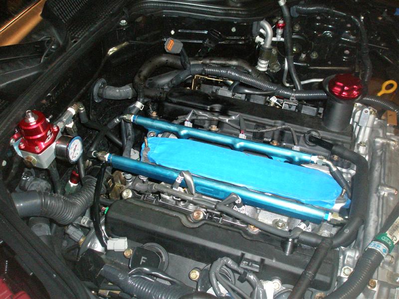
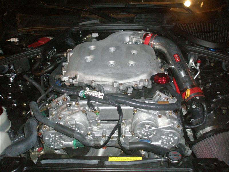
Before beginning the electronics installation, a few words about the �earth ground� kit you can so obviously see in some of the other photographs. There have been quite a few discussions on the different threads regarding the practicality of these wires. Knowing a little about avionics and signal processing, we have thought it prudent to provide a �common ground reference� to minimize �background noise� and to reduce the �noise-to-signal� ratio. We don�t know the exact values of the information transmitted in the various devices on the car but we thought that, at the very least, it would do no harm and might very well make a difference given the additional demands the supercharger will place on the processing of data to produce accurate signals to the injectors, the spark advance, the throttle, etc. We placed a �common ground reference� at the site of most of the sensors on vehicle and interconnected them around the engine and to the negative terminal of the battery. Further, we ran a line into the passenger compartment and all the grounds from the UTEC, the factory ECU, and the Innovate gauges were connected to this. If nothing else, it looks pretty cool with the thick red wire and nylon overwrap.
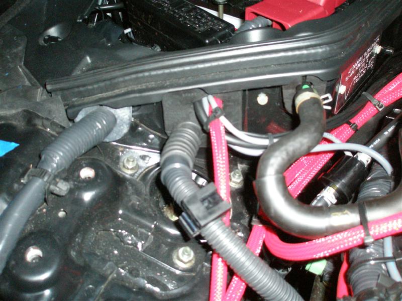
So, we now return to our automotive dungeon and finish the supercharger installation. The first step is to run the remaining sensor wires through to the passenger compartment. The Manifold Air Pressure sensor supplied with the UTEC is quite small so we used a T-fitting on the small vacuum line that runs from the front of the plenum to the fuel pressure regulator.
The electrical line leading off of the MAP sensor is very long and will reach all the way into the passenger compartment and the UTEC with no re-wiring. The Boost pressure sensor that came with the Innovate SSI-4 kit has a larger bore so we attached it to the PCV valve line that you can just see in the picture above. It has a very short electrical attachment of three wires. We �grounded� it to the �common ground reference� in the battery compartment and then ran the sensor wires into the passenger compartment. The access into the passenger compartment is through the wire loom port under the passenger side cowl. If you remove the plastic bits around the battery and the one next to the windshield you can see the rubber cap over this port. Pull it up off of its plastic retainer, cut a small slit into it, run your wires through it, re-attach it to the plastic retainer and then snap the whole thing back into place. We also sealed the wires and the slit with some silicon sealer and then replaced all of the plastic covers. Next came the installation of the UTEC. The UTEC is attached to the frame holding the factory ECU and fits back into the stock location. You should attach a USB cable (or the serial cable) and the Molex wires before installing as you can�t reach that part of the UTEC once it is in place. Now, I am not sure how much room is present in the earlier models but we found that there is an electrical control box on the side of the ventilation fan that interferes with the UTEC so we bent the frame and its attaching points outward toward the fender and �wiggle fitted� the assembly into place. It may also be necessary to remove a protective plastic housing that goes around the wire loom the exits to the door (this gives a good deal of space and does not appear to compromise the wire loom). The electrical supply to the cigarette lighter is rated at 15amps and we cut into this to power the UTEC, the SSI-4 and the gauges. The ground was the aforementioned �common ground� we installed earlier.
The gauges are mounted in the central console and I used a piece of black plastic foam with a solid backer that allows a friction fit that can be easily removed for any needed work.
We only have the Boost and AFR and rely on the stock gauges for all other information. We may need to add more later but this will do for now.
So, come to end of our saga in the garage. We have now �buttoned� everything up and will head to Houston next week to get SGP to work their magic on our little car.
And, when we return, we will post the dyno numbers (plus any additional �fixes� or recommendations that SGP has for us). We can�t wait�����..
I do appreciate everybody's patience with this write-up as we had difficulty with loading the pictures and I am sure that it was way too long. I hope that this helps at least one other member of this community join the ranks of FI.
They do. They are Wolo horns with a small seperate compressor. It gives a MUCH louder sound on the same power. You can get them online. They have saved my butt numerous times in my G. For some reason, the Diamond Graphite renders my car invisible to idiots.

Originally Posted by Lady Jax
They do. They are Wolo horns with a small seperate compressor. It gives a MUCH louder sound on the same power. You can get them online. They have saved my butt numerous times in my G. For some reason, the Diamond Graphite renders my car invisible to idiots.
Which model horn is it?
Model 418 'Powerhouse'. Just don't get the JC Whitney LED lights.
http://www.wolo-mfg.com/air.htm
And you can't even see it behind the bumper fascia ! ! !
http://www.wolo-mfg.com/air.htm
And you can't even see it behind the bumper fascia ! ! !