When you click on links to various merchants on this site and make a purchase, this can result in this site earning a commission. Affiliate programs and affiliations include, but are not limited to, the eBay Partner Network.
Basically done. The only thing stopping me from firing it up is the catch can... Well, I could just ignore it for the sake of getting it running but I'd have to take the intake off again to hook it all up, so I'll wait til next weekend...
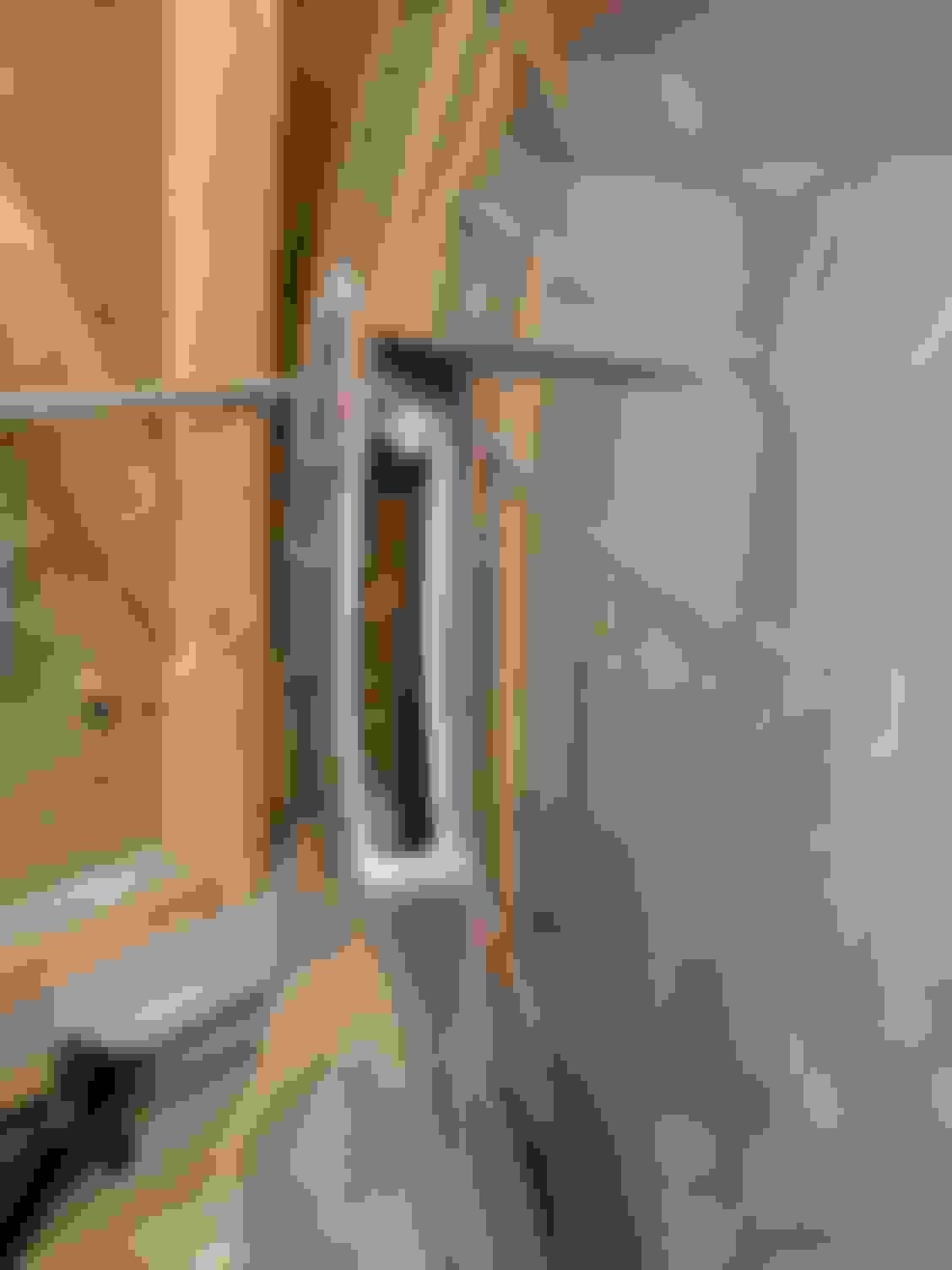
First photo is for Dark. That's the stock filler joining up with the silicone hose,
I had some spare heat tape lying around so I gave the washer/pumps some protection. I'll monitor it for a while, but I'm sure this is overkill. Didn't take long so I'd rather be safe than sorry.
Took the angle grinder to this section of the bung weld to give the coupler a little more room to move up as it was pinching a little.
And this is the air guide. It's thin and flimsy material but it's sturdy in the right places. I can always replace it with thicker material later now that I've got the shape right.
That's it. Traction oil in, all hoses and pipes are connected (except catch can and intake) and my ECU settings ready to go. Can't wait.
I suspect that will be a huge help … (I say this in the most positive / happy / non-hating way) I dont know that the tape will be enough. I say this because you are going to be hitting that reservoir (essentially) with 220degree hot air as long as the car is driving and I speculate the tape will heat-soak.
I say this because my battery is right behind my radiator and the battery gets hit with hot air quite bit and is hot to the touch (almost too hot to touch) after I run the car.
If I were in your shoes - I would keep it exactly how you have it and run the car and see how it does ‘real world’ - if you have to relocate it or put some sort of different insulation or heat sheid you can.
Looking good, thanks for that pic. Our locations vary just a tiny bit (maybe an inch or less) so I'm sure I can make it work.
I have actually given the cooler situation a little thought, maybe install the oil cooler horizontal in the spot you have the PS cooler and vertical mount the PS cooler in front of the washer tank. I also want to incorporate these somehow.
I suspect that will be a huge help � (I say this in the most positive / happy / non-hating way) I dont know that the tape will be enough. I say this because you are going to be hitting that reservoir (essentially) with 220degree hot air as long as the car is driving and I speculate the tape will heat-soak.
I say this because my battery is right behind my radiator and the battery gets hit with hot air quite bit and is hot to the touch (almost too hot to touch) after I run the car.
If I were in your shoes - I would keep it exactly how you have it and run the car and see how it does �real world� - if you have to relocate it or put some sort of different insulation or heat sheid you can.
Otherwise things look great!
Of course, man. Appreciate the input.
I was thinking that cooler would have to be 100% efficient to shift 100C from the oil to the surrounding air, which they aren't, so it'll be somewhere between ambient and 100C. On a 40 degree day that'll still be at least 60 which I agree is already getting pretty warm. I've got plenty of aluminium sheet left over so we'll see.
I'm going to put a thermometer there and monitor. There'll be plenty of safe time while I'm tuning.
That might work, Dark. Keen to see your results. How many rows is your cooler?
Also, I'll need to keep my reflectors capped. Air would just go in the grill and blow straight out the side in my current config
The saga continues... Ordered a flex fuel sensor. I'd intended on installing one eventually, but was just going to run on E85 for a while so didn't think it would be necessary. It's still not necessary, but it'll help the tuner know exactly what he's working with at the time and we can put in some basic scaling as a precaution in case I get some lower grade "E85". Hell, we might as well do the multi-fuel tune.
It looks like I've still got plenty of space behind the plenum to mount it to the firewall, so it'll sit between the rail return and fuel pressure regulator- I just need a few push lock fittings. I've still got a spare wire from when I pulled the grommet apart so signal/ground are covered. Just need a switched 12V source.
Also ordered a couple of 02 bung blanks to replace my secondary 02 sensors which are doing absolutely nothing now (primaries have Haltech WBs).
I don't have one yet as I'm on hold for a while, but was planning on getting a 13 row maybe?
I have a longer nose so I definitely have room to play around with, but one thing I want to look into is a Greddy oil filter relocation kit, otherwise my oil pan would get covered in oil every time it's changed.
I went 25 row and I'm pretty sure you could get it to fit (inlet/outlet on either side of the crash bar support) with what you'd suggested. If you use the bottom of the crash bar as a reference, the intercooler would actually go lower so there's plenty of room.
What bumper are you running btw?
I bought a Z1 undertray a while back. They're a bit of a pain to install/remove when you do the whole thing, but just oil changes are a breeze.
Also, I've printed out that part. PM me your deets and I'll get it sent.
I have this one, basically a copy (slightly shorter version) of the Nismo type E. I also just installed the Z1 panel, nice piece. My bumper probably extends about 5-6 inches passed the Z1 panel.
Thank you so much, I will send you my info in a bit.
Update... Fired up and idling nicely now. Actually it's idling better than it did when it was NA.
Reset fuel pressure (43.5psi no vacuum), dialed in the fuel table (just around the idle cells) and then the idle position table then it was spot on. The rest of the fuel table is going to take a while to road tune because lambda target is laughably out, but thanks to E85... no knock yet. That and super conservative ignition timing. And low boost. Anyway....
IATs are staying low (proper CAI) as they should for 17C ambient, but there's still a fair bit of heat soak from the headers. I'm definitely going to wrap the intake pipe in gold tape, but I really need a heat shield on the headers. That'll have to wait for when it gets a full rebuild.
VVT is still out with the new phasers so PID tuning is the only solution now.
The poor missus and neighbours are going to have to deal with a bit of garage tuning for the next couple of weeks
NICE! Not kidding on the headers, I knew it was getting hot, but I found its deteriorating the reflective heat sleeve on my A/C line and wideband harnesses. I need something more robust for the meantime, when the time comes I'll get the headers coated and create a shield for the top of them.
Everything I've read suggested it doesn't really matter on a low boost regulated return system (with much larger injectors). 43.5psi/300kPa is widely used across many configurations. Also meant that I could just plug in ID's dead time figures for 300kPa. Next jump was 58psi/400kPa. I know I could just adjust them proportionally but didn't see the need.
Once I hand it over to my tuner it doesn't matter anyway. Happy to go with whatever he suggests. This is just to make the drive mine to his.
I've flattened the whole table out to 15 degrees until it's dynoed. Idle ignition timing is doing its thing and dropping it back a touch to 7-8 degrees...
Update: Just spoke to my tuner. He's happy with 300kPa. ECU knows fuel pressure is MAP referenced at 300kPa so it's covered in the model too. The other reason I reached out was the VVT. He's convinced it's not a blockage based on behaviour- needs feed tables and/or PID tuned to match target. Fingers crossed that's how it plays out!
So of course there's always some kind of bug to iron out but I'm really scratching my head on this one. I was hoping to be able to diagnose without removing the SC, but I'm running out of ideas.
I'm getting a pretty serious oil leak on the left bank (US driver) which initially I thought was due to a dodgy job I did on the upper oil pan RTV. I realised after I'd put everything back together that I went on the wrong side of the bolts at the front that are inside the case. That said, it's not been an issue the whole time it was NA, but neither had I noticed any oil leakage so this is new regardless. Natural assumption was increase crank case pressure was causing it to blow out. BUT you can see in these photos oil is found much higher than that position so it was either a) explosive leakage to make it that high OR b) it's coming from higher up.
I didn't get a photo but I could see oil has dripped from the top of the AC compressor down the back and side to where it's pooled there.
That's engine oil underneath the first header bolt...
Heater pipe bracket
I checked the VTC solenoid- dry. I used a wifi scope to get down beside the valve cover and while it wasn't conclusive (images are pretty grainy, like photo above), I don't think it's the valve cover gasket (brand new and used a little RTV up front). So, I THINK it's blow by from the dipstick channel. Is that a thing?!
The last test was after I drilled out the PCV so it's free flowing (tested before and after - no difference). The catch can is all routed properly so there should be negative pressure on the vent hoses, especially under boost.
I'm considering unbolting the AC to get a better look at the block because at this stage that will probably be easier than removing the SC, even though I may still have to do that.
Update: I managed to move the AC forward a little to get a better view and it's definitely coming from the top of the head somewhere, but I couldn't quite make out whether it was coming from the dipstick or the valve cover. I also forgot some important details:
This is not happening at idle. I can leave it idling for ages and not have new spillage. Given that it's only happening under load/higher rpm, it's either increased case pressure and/or increased oil flow.
The closest valve cover bolt was properly torqued and still tight. Even if it wasn't, I don't think the volume of oil that was coming out would be possible there
I strapped a GoPro under the car on the previous test to confirm if there was any 'spray' around the upper oil pan. There wasn't, and even though the light wasn't great, it still captured dribbling and the odd drop that would have come from around the AC compressor
My crank venting system involved using a Y fitting used a 6AN fitting to connect the right bank and a 6AN to 10AN expander to accept the left bank. So, even though the SC should have been creating negative pressure in the system, I guess it's possible that the 6AN to 10AN was too much of a bottle neck and didn't allow it to properly vent? That's just a lot more pressure than I expected.
I'd bet it blew out of your dipstick. Same problem I had when I went boost recently and oil in nearly the same locations. Ended up switching everything to -10 lines for my catch can and adding a valve cover breather here https://www.c-f-m.com/performancepar...Z-768p1663.htm
Check for any oil around the spark plugs/coil packs. Could also be a leaking seal there. If it's coming out the dipstick, that's a lot of crank pressure. Try placing some bits of rag in different spots (after cleaning the area) to see if you can find the source by which one gets wet.
Double check all your vacuum lines to make sure one isn't still accidentally hooked up so it sees boost, that could pressurise your crank (been there).
Mate, I noticed the breather on one of your last vids and ordered one yesterday!
What's your catch can config?
It's a Dynosty catch can with -10 fittings and lines with a PCV delete fitting on the passenger valve cover and adapter for the driver valve cover (US driver position).
Check for any oil around the spark plugs/coil packs. Could also be a leaking seal there. If it's coming out the dipstick, that's a lot of crank pressure. Try placing some bits of rag in different spots (after cleaning the area) to see if you can find the source by which one gets wet.
Double check all your vacuum lines to make sure one isn't still accidentally hooked up so it sees boost, that could pressurise your crank (been there).
Yeah I checked plug 2 at the time. Dry as a bone. Vacuum lines are triple checked- they're all good.
At this stage I'm 90% sure it's because I restricted the 10AN line so I'm going to do a run with it disconnected so it can vent to atmosphere.
In terms of fixing this... I'm either going to just vent the right bank (PCV) to atmosphere with a filter and buy a 10AN banjo to connect the left bank to the catch can (which will still be routed back to the SC) OR the more expensive route is buy a 10AN banjo, 10AN Y fitting and 10AN to 6AN reducer (for the right bank) and then it's a complete system... I'll do some testing before I commit to anything.