When you click on links to various merchants on this site and make a purchase, this can result in this site earning a commission. Affiliate programs and affiliations include, but are not limited to, the eBay Partner Network.
Re the catch can, I ended up going with the Radium. It was $100 cheaper here than the Mishi. In one of the images on Chase Bay's site, it looks like they've got two intakes into one inlet. I'm sure it'd be fine but I'll deal with that later.
Re angled spacer- I mean I get the logic behind it, but I really don't like the idea that the bolt heads (and nuts now) are no longer square with the plenum surface. All the load is at the front of the bolts (relative to front of car) and I assume will dig into the plenum a little. I did the dirty maths (yes, Maths, I'm Australian) and it's about a 0.7 degree slope. If I could do it myself, I'm pedantic enough to machine the plenum to match but I'll live with the irrational anxiety instead.
A Y-fitting (or T) should be fine for NA but I'd like dedicated ports for FI.
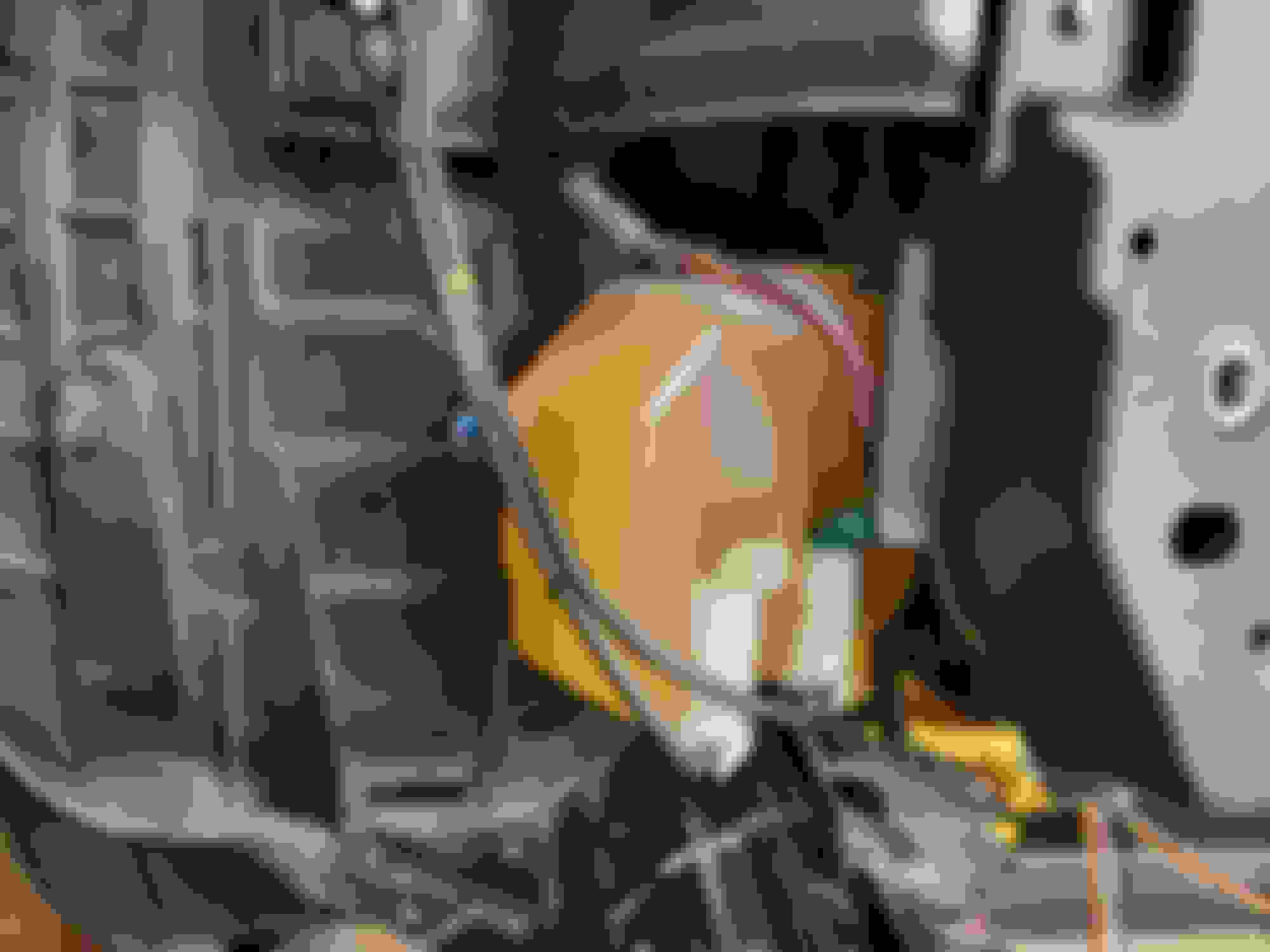
Anyway on to the adventure of the day, the Greddy tank fits perfectly in the stock location angled inward.
Lines are perfect, harnesses work, we will have to figure out how to fill it or create a remote filler neck for it.
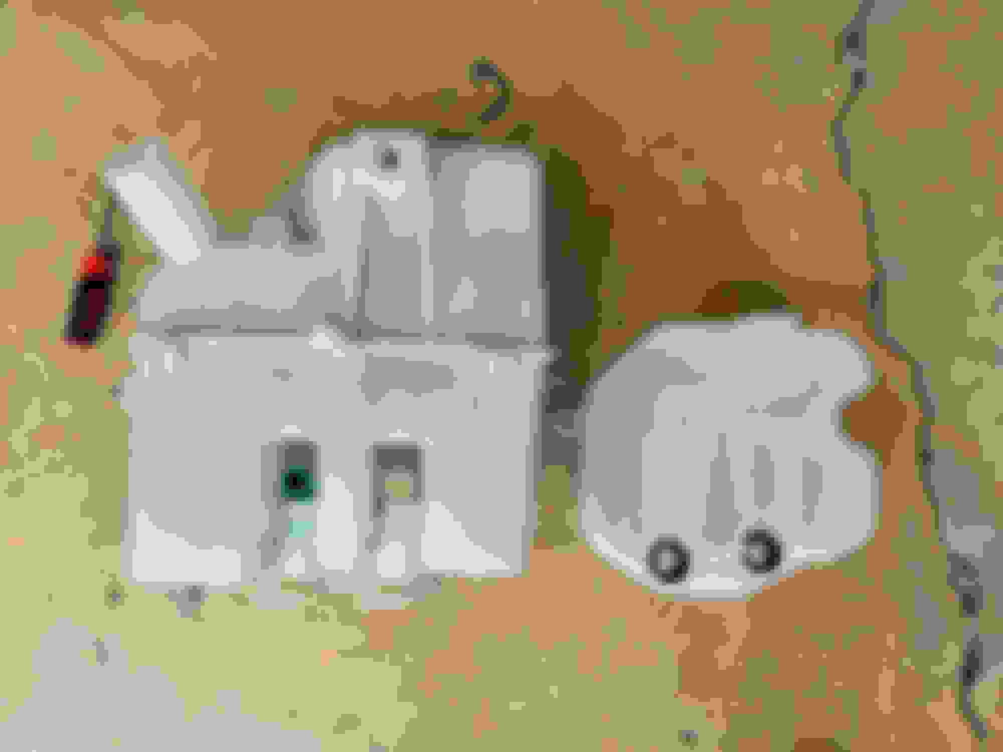
Now on to the adventure, they provide you with grommets, but they don't fit our pumps.
I didn't realize this until I filled it, so I made a mess, got myself wet multiple times trying to figure this out.
Looks like here you can't source just the grommets, they come with the pumps.
So instead of trying to go to the stores trying to match something up, then deal with wiring or whatever else would be required, I improvised....wrapped the nipples in electrical tape to make them thicker.
So far it's been dry and since it's compressed in there, it should be ok, if it leaks I'll have to figure it out.
Brackets just made with some stuff I had around, outer one is steel going to stock location. Inner one is aluminum and attaches to the clip for the PS cooler lines.
This means I can put a GReddy sticker on my car now, right?
Measure twice, cut once kids. So mad at myself for this one especially because if I'd gone another 20-30 degrees lower, there's plenty of space. It's salvageable but irritatingly dumb...
Hell yeah lol, LMK if you find some cool way to extend the reservoir. Best idea I've thought of this far is getting the relocation kit from a mk7 Golf R and retrofit that somehow.
That has a metal cap and upper reservoir.
Can't you just get an elbow for that fitting?
Unfortunately, no. The sensor has to poke through into the pathway of the air. Like the MAF, but much smaller.
I'm going to try and make some space with the line and maybe grind the nut a little. Just want to minimise rubbing. If I can solve it, I'll get another bung installed. So stupid.
Installed my new clutch slave. Switched from an 03-04 to a 05-06 (to match the CD00A). Pretty sure it's bled (air bubbles stopped long before I did), but still a touch spongy for the first third of a press.
I had to shave even more off the dipstick bracket. Capped the vent intake too.
Washer ready to go. Electrical tape to fill the void did the job, yeah.
I don't want to jinx it, because I haven't been able to test fit the bumper yet, but I may have had a stroke of luck with the coolers. I managed to bolt the bracket that was already attached to my oil cooler using a couple of bolts that secure the crash bar support. Almost like it was made for it. It's a tight fit so I'm going to shave a smidge off the back corner of the crash bar to make sure there's never any rubbing.
And even though I thought there was no chance it'd fit, the PS cooler snugs in there nicely. Less cooling potential than before, but it'll be fine. I've ordered a 6AN elbow and then just gotta make some brackets!
Haven't had a tonne of time this weekend, but made a little progress.
Took the angle grinder to the radiator support so I can angle the oil cooler back a couple of degrees.
Better shot of the cooler bracket and where it bolts up. Got some sheet aluminium to make a duct for this cooler.
Shaved down these raised spots on the rad support to give a touch more clearance.
First attempt at fabbing a bracket. Pretty dang happy with it and the position is perfect. I'd prefer a thicker gauge but it's not going anywhere.
Bottom bracket in too. I'll round the edges to make it look nice. Probably going to make a little alloy sheet to block a small gap between the rad support and the lower section of the cooler. It'll make sense when I finish it.
@DarkZ03 Re the filler bottle. My plan so far is to run a 32mm ID hose from the stock filler to the GReddy bottle. I printed an adapter to join the two. I'll let you know how it goes once I get my hands on some hose.
Sized up my oil cooler lines. Took two goes to get it spot on. The steel braid was exposed so I added some nylon sleeve and heat shrink to give them some protection from rubbing.
Coolers are both located nicely now. I'm definitely going to add a plate between the two coolers so air doesn't get wasted there. Especially because the oil cooler is actually angled away from the incoming air. I'll look to block those marked sections too.
I had to shave a little more off the rad support to angle the cooler back even more to clear the bumper (after the first test fit). A few less rows on my cooler would have been a perfect fit but it still works. The arrow indicates where the one of the reflector mount points hit the cooler. I had to dremel a bit off the reflector mount to clear.
Washer is in and completely functional. I'd prefer to have more room behind the cooler but it's hardly a blockage. My only real concern now is that the electrical connectors are facing the air flow where normally they'd be hidden behind. Dielectric grease and some extra wrapping should be safe enough.
@bealljk You know I hadn't even thought about it. It's a fair question. I guess it'll depend on how much of that heat is transferred. I'll have to keep an eye on it while testing and maybe throw on some gold heat tape. Definitely worth protecting the pumps! Initially I'd considered adding some sheet aluminium between the two, but that was mainly to create a smoother path for the air and keep **** off the pump connectors. Might need to revisit.
Also, I think I hit a snag with my catch can situation. I bought a Radium single can which is designed to handle the right bank PCV and route it back to the plenum. I had intended to route the left bank vent to my catch can using a y-piece for the inlets. This probably would have been fine while NA, but under boost it looks like that will create positive pressure in the can/line and push air back into the left bank valve cover (where there is no one way valve, of course). Makes sense now that the HKS kit routes a line directly to the supercharger housing, as that would have the opposite effect and create a vacuum. What I really need is a catch between the valve cover and the SC. I'd have no problems venting to atmosphere except that a fair bit of gunk comes out of that cover so a filter would clog pretty quickly.
I think I've got it... I can run both lines to the catch can as planned (with no additional check valves), plug the plenum vent intake, and either vent the catch can to atmosphere (which relies entirely on the positive pressure from the valve covers, fine), OR run a line from the catch can to the SC intake (which creates negative pressure and will help to draw gas from the can). Only downsides to the latter are extra hose clutter and some vapour still making it's way to the SC housing.
Edit: Yep, found some old threads that concluded much the same thing. Now I just decide if more hose and fittings is worth it to create some negative pressure in the catch can... I think I'll vent to atmosphere and see how it goes.
Yup, this is what I was trying to tell you. In the spirit of how the system is supposed to work I'd rather have it in negative pressure all the time. Even my baffled can let's some stuff passed it but not much, my engine isn't in the greatest condition tho. May consider a dual can set up too.
@DarkZ03 I went back and re-read what you wrote back then on the catch cans. I'd completely forgotten about it, but yes, we're on the same page
I just used the stock filler in the stock location and a silicone hose to connect to the printed adapter. Works perfectly. I'll try and get a better photo for you.
Cool, if you want to print me one I'll gladly pay you for it lol. I had to shelf the idea and progress for the time being because my DD decided it needed a new turbo so the Z is back together and out of the garage for the time being lol.