When you click on links to various merchants on this site and make a purchase, this can result in this site earning a commission. Affiliate programs and affiliations include, but are not limited to, the eBay Partner Network.
Hi everyone, I've decided to take on a project that absolutely no one asked for. I want to take the cheapest monotube coilovers I can find, and turn them into a respectable kit by re-valving them, and possibly changing spring rates as well.
The candidate coilover kit I went with is the REV9 true coilover kit. From my research, I think this is the cheapest monotube coilover kit available. I bought them off of Ebay
The comparison suspension I'm using a used NISMO kit that I sourced from someone on FB marketplace.
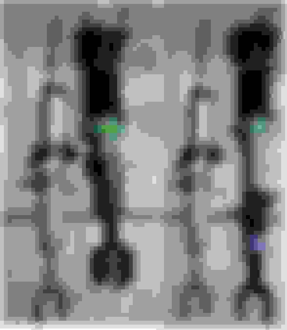
Here's a comparison of REV9 and NISMO fronts. I don't think I took a picture of the rears.
The REV9s are able to be both longer and shorter than an OEM front shock. There should be plenty of height adjustment range with these.
My rough plan is to do the following:
Dyno the NISMO shocks
Dyno the REV9 shocks
Measure spring rates for the NISMO front and rear units
Measure spring rates for the REV9 front and rear units (although advertised spring rates are probably close enough)
Use the shock dyno and spring rate information to do some rough ride frequency and damping ratio calculations
Rebuild the REV9 shocks to match the NISMO units
I should be able to post some shock dyno information very soon.
Good luck- in my experience, the materials used in high end dampers are quite a bit different than cheaper ones. Higher quality steel or aluminum with better tooling. Valving is another area that can't be ignored, with high quality adjustments for high and low-speed dampening. Just matching dyno rates is not enough- it's how reliable and repeatable those settings last on the racetrack is where those high end shocks really prove their worth.
Here are a couple shots of my dyno setup with the dampers rigged up. I own a 10 Hp Roehrig crank dyno. The lower side can use nuts/bolts to attached the OE clevis to the dyno clevis. The rod side is simple since I can just thread on a rod end.
Threaded body shocks are nice since you can use one lower attachment and just thread in a differed damper as needed.
Every now and then, a new thread will pop up that is different from all the "hey-my-car's-broke" threads. In for the results. This is something of a "black art" (mysterious). I once read a story about the Penske dyno tuned racing shocks but never got any real information on the process. Cool.
I'm glad there's interest in the technical details! I'll do a quick post on dyno charts since some folks may want to see that.
Any shock (damper) creates a force proportional to the speed that the damper shaft is traveling. So when graphs quote a speed, it's quoting the damper shaft speed. The force output of the shock is the force required to achieve that shaft speed.
So if the shaft velocity is zero, then the damper is making no force. If the shaft speed is greater than zero, then there will be some force output.
Generally speaking, when the car's suspension is traveling upward (like from a bump), the spring/damper are being compressed. That's positive force and positive shaft velocity. That's referred to as compression.
The reverse is true for rebound� when the suspension is extending, that's negative shaft velocity and negative force.
So when the shock on the dyno and being cycled up and down, that same sign convention is being used. Here's a picture of that:
That picture is basically the industry standard for looking at force vs velocity graphs. However, since there's so much wasted space on the graph, it's better to look at with "absolute" velocity. So the shaft velocity is always positive, and the force remains either positive or negative depending on which way the damper is moving. Here's a picture of that:
Those two graphs are the same data, just displayed differently. Now, how that data was physically created is important to understand as well.
A shock dyno just cycles up and down at whatever speed it's programed to achieve. The total displacement (shock travel) that the dyno cycles through is 1 inch in this case. That can be changed, but involves taking the machine apart. So in the above graphs, the target speed is 10 inches per second, and the displacement is fixed at 1 inch.
This dyno is standard crank type mechanical dyno. It's just a shaft that moves up and down to cycle the shock. The dyno can cycle as many times as the user desires, but what you see displayed in these graphs is one complete dyno cycle. The starting point of the dyno is technically -1/2'', so it cycles from -1/2'' to +1/2'' and stops back at -1/2''. Starting from a "negative" position seems to be an industry standard from the different crank dynos I've seen (don't ask me why). So, although the dyno cycled several times in real life, only one complete cycle is shown on the above graphs. To reiterate, the graphs above happened to be a 10 inch/sec target dyno speed.
In real life, a shock will see all sorts of different scenarios. It's never just a smooth up and down like the dyno provides. So, to help understand the total possible force envelop of any one damper, dyno data is gathered at many different shaft velocities. Then, the maximum achieved force at any of these individual speeds is reported. The industry generally refers to this is PVP (Peak Velocity Pick-Off). Those individual forces are plotted against their corresponding velocities to create a graph like this:
PVPs are nice because you get a really quick overview of what the damper is capable of in one simple graph.
So the spread on the rebound is interesting, Is the spread typical to see like that? Is it due to micro cavitation that is aerating the fluid, or temperature, or some other phenomenon?
That's a really good question. The short answer is that the spread you noticed is pretty typical. I've seen far worse, and I've seen far better.
All shocks are going to have some discrepancy in force output depending on what scenario the shock is experiencing. Generally it's referred to as hysteresis, which is basically the spread or lag between loading and unloading of system. I'd say there are two key items to understand when you're looking at the hysteresis loop of a shock dyno graph.
#1: What portion of the dyno cycle you're looking at.
#2: How any shock creates a force.
For #1, it's important to understand the dyno accelerates from a shaft speed of 0 to whatever the target speed is in the available dyno stroke. In this case 1'' of stroke and 10 in/sec shaft speed. So when you look at that graph, you see all the speeds from 0 to 10 in/sec. The dyno starts at zero, accelerates to 10in/sec, slows back to zero, then changes directions and repeats the same cycle.
So here's a chart of what the dyno is doing:
That pattern is completed several times, and one full cycle is graphed. I've highlighted on the previous graph where in that cycle the rebound portion of the curve is:
The compression side is the same story.
Now, for #2, it's important to understand what is happening inside a shock. At the most basic level, a force is needed when attempting to pump oil through a hole. Just like blowing through a straw, the smaller the straw is, the harder you have to blow. In real life, the shock piston is being pumped through the fluid, not the other way around, but conceptually it's fine to think of it as pumping oil through a hole.
The viscosity of the fluid and the size of the hole are they key factors here. I think it's important to understand that the oil/fluid being pumped through a hole becomes thicker the faster it's being pumped. This is true of any size hole and any fluid. The smaller the hole, the more noticeable that effect is. Here's dyno graph of oil flow only through a bleed hole:
The size of the hole isn't changing, but the oil is getting thicker the faster it's being pumped through the hole. That's why the force output increases exponentially. Anytime you see a damper graph that has this curvature shape, you know the oil is being pumped through a bleed hole only.
Traditionally, most dampers will have some sort of bleed hole, and some sort of shim stack (steel disks) that cover the main piston holes. The shim thickness and orientation create a spring rate (stiffness). For example, a thicker shim stack will create a stiffer spring rate covering the piston holes. As the shims bend, the oil flows through the main piston holes. These holes are relatively large compared to a "bleed" hole.
Here's a visual of a shim stack on a damper piston (not my work, I got this from google images):
So here's a breakdown of what I'd say is happening with that same dyno graph I've been using:
Here are some very general rules: The smaller the bleed hole, the larger that spread (hysteresis) is going to be. So when the shim stack opens, it will be flatter and have less hysteresis than flow through a small bleed hole. I'd also argue that the thinner the oil is, the less hysteresis you'll see when the oil is pumped through a small hole.
Also very important is how well the internal pressures are being controlled. If local pressures drop to near zero, then the oil becomes more like air (cavitation). Technically speaking when the oil "cavitates" it's actually boiling locally. Low pressure = low boiling point.
Mono-tube shocks do a great job of controlling the overall pressure on the oil. Twin tube shocks may or may not be gas pressurized. If it's not pressurized, then you'll end up with major hysteresis loops because the oil is cavitating occasionally. That's why mono-tube shocks are preferred for performance applications. There's more to the story than just that, but it's a good starting place.
That post ended up longer than I thought! Thanks for reading.
Okay, so here's the front NISMO shock vs the front REV9 adjustments.
Some things to note:
-I'm counting fully stiff (closed) as zero. The adjuster is tightened (clockwise), then every click is counted as the adjuster is opened (counter clockwise).
-The REV9 front coilover has 16 clicks of adjustability.
-This style adjuster is an "open" bleed, meaning it adjusts both compression and rebound simultaneously. This is the simplest of all damper adjusters.
-NISMO front is black, and the REV9 adjustment sweep is all orange.
Here's a screenshot of the results
The NISMO shocks are not adjustable of course, so it's just one line.
My thoughts:
-The REV9 damper curve is fairly typical for aftermarket coilovers from what I've seen. Meaning, the rebound damping is many times stiffer than the compression damping. This is a typical OE style setups that prioritizes cabin comfort over pure handling/grip. Generally speaking, soft compression damping allows for large suspension movements over bumps, then the stiff rebound controls (slows) the return motion of the suspension. This is the setup used for cabin comfort, meaning the least amount of up/down movement in the vehicle cabin. This style of damping, coupled with soft springs, makes for a very plush ride (think 1980's Cadillac).
-That said, the REV9 adjustment range is ENORMOUS. This is also typical of aftermarket coilovers I've seen. The REV9 rebound range can go from significantly softer than the NISMO, to a fair bit stiffer than the NISMO. I would imagine the REV9 fully stiff setting to feel pretty harsh. But, there's plenty of room to find a comfortable setting.
-The adjustment range on the compression side is much smaller than the rebound side. That is because the compression shim stack is very soft, and therefore opens at a low damping force. In other words, the compression shim stack opens early at every click setting, making the click settings relatively insensitive. When you adjust a REV9 coilovers, you're mostly making rebound adjustments, with only a slight compression adjustment.
Both the rebound and compression of the rev9 shock seems to be very linear. There is not much transition from bleed hole to shim stack. That is interesting also.
My 1st introduction to how dampers worked was when I was racing 1/8th scale Nitro RC buggies and I wanted to tune my car's shocks to handle the jumps better while still maintaining decent handling in the corners. To be honest I only had an elementary understanding of what I was doing, but the same principles apply to real cars. I tinkered with the bleed hole plate options, different viscosities of the fluid, and coil springs until I found a combination that worked nicely. It really made a big difference in the handling. The car was easier to control, less wheel hop and bump steer while also being able to get big air and take the landing hit.
The science behind this stuff is fascinating. I never even considered the possibility of cavitation in a shock/damper.
Thanks for posting about this stuff! It's awesome! Are you an engineer/developer?
Cheers!
-Icer
Thanks for the interest! Yeah, I did about a 10 year stint in motorsports where I was doing damper development. Now I work more in the OE type world, and not with suspensions anymore. However, I still wanted to do some shock related projects, hopefully with the ability to turn it into a side hustle eventually.
I've known some RC car guys, and I've always been impressed how into vehicle dynamics they always are. For example, there have been RC car shock dynos made and used:
RC guys seem to always be really knowledgeable about suspension geometries too. Roll center, jacking, camber gain etc etc. I've always been really impressed by that niche.
And here's the rear NISMO shock vs the REV9 rear shock:
The same basic trends exist in the rear as in the front. The adjustment mostly affects the rebound since the compression is so much softer. That rebound range again is quite large.
One thing that's interesting is the rear dampers have fewer available clicks (12 rear vs 16 front). This was consistent across the four shocks, so I don't think this is some sort of error. I can't imagine the internal thread pitch is different between the different shafts, so I'm assuming the length/shape of the bleed needle is different front vs rear. I'd have to take the assembly out of the inside of the shaft to be sure of that.
The next step is to take these apart and see what's necessary to modify the builds. Stay tuned for that!
These shocks aren't exactly meant to be opened easily. They don't have a valve to release the nitrogen pressure. Therefore, the easiest way to open them is by drilling a hole in the nitrogen reservoir cap. Firstly though, unscrew the shaft bearing cover (plate that's screwed onto the bearing).
At this point the damper is still pressurized. Now, drill a hole in the nitrogen reservoir cap.
Okay, now that the shock is depressurized, the shaft bearing can be pushed down. Then pick out the circlip, and pop the damper shaft assembly out.
Here's an update with the piston and shims disassembled:
This is my setup for working with the damper shaft. Just a generic rod end screwed onto the shaft.
Close up of the piston assembly.
And here's the piston and shims completely disassembled:
As expected, the compression side of the shim stack is thinner and has fewer shims than the rebound side. This leads to a softer compression curve overall. Also, the piston holes on the rebound side are smaller than the compression side. This is very typical and helps create a rebound biased shock curve.
Even those these are VERY cheap dampers, I have to say, there's nothing obviously wrong with these units. It's certainly a good enough platform to work from and re-valve.
 03-26-2024, 07:51 PM