
Dual rear calipers ebrake


Registered User
Joined: Jul 2008
Posts: 12
Likes: 0
From: Ladson, SC
Here's a link to the 240sx ones he sells. I have a friend in Myrtle Beach, SC who bought some of his Z and G ones. I'll try to get pics from him.
[URL="https://www.facebook.com/photo.php?fbid=419783358035787&set=pb.357519507595506.-2207520000.1369413912.&type=3&theater"[/URL]
[URL="https://www.facebook.com/photo.php?fbid=419783358035787&set=pb.357519507595506.-2207520000.1369413912.&type=3&theater"[/URL]


Bump, is that guy in Canada still making these? I'd be up for a pair. I have a buddy who works at a machine shop who could easily make them but I'd rather just pay the $200 than have to deal with all the measuring and designing.

Registered User
Joined: Apr 2010
Posts: 10
Likes: 0
From: New jersey
well, i got tired of waiting for one of these guys to put out a bracket so i went ahead and fabbed up my own.
its pretty raggedy.. im no machinist ... more or less, im a complete noob. i used a reciprocating saw to make the cuts and hand held drill to make the holes. but it works and thats all i care about.
Check out the pics
vids of it in action at East Coast Bash in NJ a few weeks ago.
if there is enough interest i might be able to get a few duplicates made and sent out. let me know what you think.
Last edited by Jordanak; Jul 23, 2013 at 11:03 AM.


Q1:
What material did you use?
I ask because i don't see any radius's at the machined step location??
E-brake forces are quick and high, not continuous because you release the E-brake in short intervals...that being said i ran stress testing calculations and found fatigue to be a concern.....
you have a straight 90 degree step with out a radius it seems???? I can't completely tell from the pictures..

INSPECTION INTERVALS:
I wouldn't say dont use it, but i would be very very proactive on inspections before and after every drift event.
I would go as far as remove it, inspect it with a high power flash light for cracks, warping, etc...use a steel straight edge to ensure its still flat and not warped, etc...etc...
Q2:
What did you use as a spacer for the OEM brake caliper back to its OEM knuckle mount location??? You need a spacer the thickness of the knuckle mounting plate section dont you?
-J
Last edited by JasonZ-YA; Jul 24, 2013 at 05:50 PM.

New Member
Joined: Jan 2011
Posts: 17
Likes: 0
From: Lithuania
Great work, this is very similar to the one i designed.....
Q1:
What material did you use?
I ask because i don't see any radius's at the machined step location??
E-brake forces are quick and high, not continuous because you release the E-brake in short intervals...that being said i ran stress testing calculations and found fatigue to be a concern.....
you have a straight 90 degree step with out a radius it seems???? I can't completely tell from the pictures..
INSPECTION INTERVALS:
I wouldn't say dont use it, but i would be very very proactive on inspections before and after every drift event.
I would go as far as remove it, inspect it with a high power flash light for cracks, warping, etc...use a steel straight edge to ensure its still flat and not warped, etc...etc...
Q2:
What did you use as a spacer for the OEM brake caliper back to its OEM knuckle mount location??? You need a spacer the thickness of the knuckle mounting plate section dont you?
-J
Well, it's steel lol. Don't know what kind exactly. I let the machine shop decide according to my application. Yeah, the step is 90 degrees. The plate goes from 20mm thickness to 12.38mm. Not sure what radius you mean thou.
Q2
I used a 5mm washer and replaced oem bolts with 10.9 grade that are 5mm longer. And yes, you do need a spacer behind stock calipers.
I'm open to any suggestions about the bracket so if you think I should change anything let me know.
Well, knowing the material is very important for calculation, best to try and ask the shop what they used exactly.
as for the fillet radius im describing, i created a quick drawing to help show where im saying its best to have one below.
its better for the machine shop to do that last pass with a fillet radius'd cutter so to NOT leave a 90 degree corner.
corners like that are perfect crack propagation points in the material. Adding a radius is a good fatigue detail to design into the part. Radius in red, crack location can start at corners shown with red dash arrow.
See here:

Below are basic design principle images that help explain stress concentration via lack of a fillet radius:
Design example 1:

Design example 2:

So again, i dont know your material, and i don't have a tested sample data chart like the example #2 image, but to explain how it works:
I do have that you started with 20mm thickness part and machined down to 12.38mm is what you stated in the prior post.
-- so, lets assume the ex #2 image "testing" applied to your material and you went back to your machine shop and had them do the following based off example #1 image of r = .5 x T :
Fillet radius = 6mm
Thickness stayed the same at = 12.38mm
you essentially end up with 6/12.38 ~ .485 so lets just say .5 or half (R/T).
On that table you would look at a stress concentration of about 1.51 it seems if you follow it over to the LH side of the graph on ex image #2.
that means whatever your load is, its 1.5 times that at that location "WITH" a fillet radius........now can you imagine with NO fillet radius?!?!?

-J
as for the fillet radius im describing, i created a quick drawing to help show where im saying its best to have one below.
its better for the machine shop to do that last pass with a fillet radius'd cutter so to NOT leave a 90 degree corner.
corners like that are perfect crack propagation points in the material. Adding a radius is a good fatigue detail to design into the part. Radius in red, crack location can start at corners shown with red dash arrow.
See here:
Below are basic design principle images that help explain stress concentration via lack of a fillet radius:
Design example 1:
Design example 2:
So again, i dont know your material, and i don't have a tested sample data chart like the example #2 image, but to explain how it works:
I do have that you started with 20mm thickness part and machined down to 12.38mm is what you stated in the prior post.
-- so, lets assume the ex #2 image "testing" applied to your material and you went back to your machine shop and had them do the following based off example #1 image of r = .5 x T :
Fillet radius = 6mm
Thickness stayed the same at = 12.38mm
you essentially end up with 6/12.38 ~ .485 so lets just say .5 or half (R/T).
On that table you would look at a stress concentration of about 1.51 it seems if you follow it over to the LH side of the graph on ex image #2.
that means whatever your load is, its 1.5 times that at that location "WITH" a fillet radius........now can you imagine with NO fillet radius?!?!?
-J
Last edited by JasonZ-YA; Jul 25, 2013 at 07:52 PM.
as for your answer of Q2, that makes sense with a part that started 20mm and ended with a 12.38 step, i would have guessed a 5-6mm spacer was required....look at the split in the numbers, not exactly a half cut part.
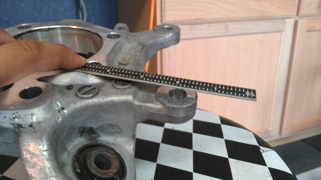
I have measured the knuckle of the 350z and found the oem flanges for the oem brake mount location to be .300 inch below the surface of the hub mounting point or the surface where this bracket gets installed....
So .300 is about 7.6 mm in difference, with your joggle you got it all pretty darn close. ie, 20 - 12.38 subtraction....
See my measurements shown here of what im trying to explain:

-J
I have measured the knuckle of the 350z and found the oem flanges for the oem brake mount location to be .300 inch below the surface of the hub mounting point or the surface where this bracket gets installed....
So .300 is about 7.6 mm in difference, with your joggle you got it all pretty darn close. ie, 20 - 12.38 subtraction....
See my measurements shown here of what im trying to explain:
-J