
Back home lets build!


its kinda not really needed but i solder as well as crimp any connectors i use and any splicing i solder i prefer doing it that way with heat shrink. i have a slight system in it thats a 4 guage wire but the amp is only 150 watts rms per channel and amp only can fit a 8 guage wire in it so i really dont need more then 4 guage battery wire even though it is kinda long, even during cranking it dosnt even start to get warm.
the speakers are coming out though since i really dont listen to it now, cant hear over the exhuast and fuel pumps.before everything i used to listen at radio level 18 on my kenwood hu, that was enough to drown out road noise around base with the windows down. now i have to crank it up to 22 to hear over the fuel pumps and they are still very prominent, only way i can hear over exhuast is about level 24 where it dosnt sound as good and i have to keep the car under 2k rpms. if i punch it theres probably not many feasible audio setups that could drown out the exhuast, not enough room left in the car with everything i added in lol.
the speakers are coming out though since i really dont listen to it now, cant hear over the exhuast and fuel pumps.before everything i used to listen at radio level 18 on my kenwood hu, that was enough to drown out road noise around base with the windows down. now i have to crank it up to 22 to hear over the fuel pumps and they are still very prominent, only way i can hear over exhuast is about level 24 where it dosnt sound as good and i have to keep the car under 2k rpms. if i punch it theres probably not many feasible audio setups that could drown out the exhuast, not enough room left in the car with everything i added in lol.
finally managed to get spare block apart and inspected everything, stupid division change of command practice >.<, so it should go to the machine shop tomarrow. using a precision straightedge and feeler guages dosnt seem the engine needs a line hone theres no gaps in alignment. the bearings did show some wear like there was mayby slight misalignment, but also slight hot spots on crank which could have possibly caused the odd wear on the bearings(not the spots themselves but engine mayby being overheated slightly.) also did have a washer destroyed in one combustion chamber so who knows im going to have the machine shop double check as well.

Registered User
Joined: Nov 2011
Posts: 47
Likes: 0
From: Boston
its kinda not really needed but i solder as well as crimp any connectors i use and any splicing i solder i prefer doing it that way with heat shrink. i have a slight system in it thats a 4 guage wire but the amp is only 150 watts rms per channel and amp only can fit a 8 guage wire in it so i really dont need more then 4 guage battery wire even though it is kinda long, even during cranking it dosnt even start to get warm.
the speakers are coming out though since i really dont listen to it now, cant hear over the exhuast and fuel pumps.before everything i used to listen at radio level 18 on my kenwood hu, that was enough to drown out road noise around base with the windows down. now i have to crank it up to 22 to hear over the fuel pumps and they are still very prominent, only way i can hear over exhuast is about level 24 where it dosnt sound as good and i have to keep the car under 2k rpms. if i punch it theres probably not many feasible audio setups that could drown out the exhuast, not enough room left in the car with everything i added in lol.
the speakers are coming out though since i really dont listen to it now, cant hear over the exhuast and fuel pumps.before everything i used to listen at radio level 18 on my kenwood hu, that was enough to drown out road noise around base with the windows down. now i have to crank it up to 22 to hear over the fuel pumps and they are still very prominent, only way i can hear over exhuast is about level 24 where it dosnt sound as good and i have to keep the car under 2k rpms. if i punch it theres probably not many feasible audio setups that could drown out the exhuast, not enough room left in the car with everything i added in lol.
It sounds like you need some noise canceling headphones for that beast! lol.
I dont mind it lol, ive never seen corrosion get inside a properly soldered anything. Seen tons of crimps fail to corrosion though hence why i solder as well. As long as it is properly fluxed then impuritys are burned away and that connection wont fail from corrosion. Its def not going to pull apart
Registered User
Joined: Nov 2011
Posts: 47
Likes: 0
From: Boston
I dont mind it lol, ive never seen corrosion get inside a properly soldered anything. Seen tons of crimps fail to corrosion though hence why i solder as well. As long as it is properly fluxed then impuritys are burned away and that connection wont fail from corrosion. Its def not going to pull apart
Just one example of why you should not solder connections: http://www.sailnet.com/forums/gear-m...soldering.html No Boats or Airplanes use soldered connections, all crimped(I am not talking about pcb through hole and surface mount connections). Solder turns your nice flexible wire into a hard brittle wire which will fail over time. ABYC standards: "Solderless crimp on connectors shall be attached with the type of crimping tools designed for the connector used, and that will produce a connection meeting the requirements of E-11.16.3.3.” 11.16.3.8."
"The most serious corrosion actually came from the joints themselves. THe solder had hairline cracks which had corroded and made the joint poor. In some cases, this joint had failed alltogether an you could bend the connection at that break."
Also, they do make connectors made to be soldered though I don't recommend using them. You really never want to solder a crimp connector. If you are concerned about corrosion spend the extra cash on pre tinned wire.
The reason why crimping is by far the superior method of making a good electrical connection is that a properly compressed connection (that means, the right tool, for the right size connector and the right pressure applied to the crimp) will make the wires & connector pretty much become one. Some people refer to this as a "cold weld"
This is what a proper crimp looks like if you cut it in half:
Note that there are no voids in the wire grip area for either terminal. If a polishing tool was used, you would be able to see individual strands captured in the terminal wire grip barrel. The 500 microinch or so thickness of tin plating on each strand would be visible as squashed ovals traced in the copper surface. As you can see, the wires & connector become one. It eliminates all voids between wires, thus keeping any air out. This prevents corrosion, which is the #1 problem in electrical connections. Corrosion increases the resistance of the connection, which obviously is bad.
Check out this article "This is NOT a crimper"...good information
http://www.terminaltown.com/Pages/Page7.html
This one also has a lot of good information.
http://www.aeroelectric.com/articles...rimptools.html
While soldering does "seal" most of the connection area, mechanically, it is a fairly weak connection, especially with all the vibrations of a car, which add to crimping being better. Another real problem with soldering and why the ABYC code recommends crimping over it is that in the case of a circuit or wire with high electrical loads, the solder can often heat up enough to soften... combine that with wires that are vibrating... you can get a loose hot live wire inside a car.
I doubt I can convince you otherwise but I just thought I would share this information. If soldering crimped connectors was really better, our cars and Ferrari's would come from the factory that way.
Sorry to muck up your thread I just hate seeing soldered crimp connections.
Last edited by Torgus; Apr 4, 2012 at 10:37 AM.
Thats good and all but the corrosion ive seen starts outside the crimp not inside mayby ive just never seen the "good" connectors but only thing with terminals are my battery cable and power cable for fuel pumps because they have to have it. Ive never in my life seen a aero grade or marine grade crimp connectors on a car, nor have i even seen such a connector. Most crimps i see fail either coming loose or salt corrosion since none of them come with heat shrink. At least none if the ones ive seen.
If your wire is heating up enough for soldier to come loose or eveb soften then whoever did it if fail and you need a bigger wire that can handle the load. Coming from ohio ive never seen a soldered connection fail and it is THE standard there solder and heat shrink where the only issue is salt corrosion.
If your wire is heating up enough for soldier to come loose or eveb soften then whoever did it if fail and you need a bigger wire that can handle the load. Coming from ohio ive never seen a soldered connection fail and it is THE standard there solder and heat shrink where the only issue is salt corrosion.
Last edited by jerryd87; Apr 4, 2012 at 11:07 AM.
Registered User
Joined: Nov 2011
Posts: 47
Likes: 0
From: Boston
Have you tried coating the connection with an oxide inhibitor like De OX for instance?
http://www.ilsco.com/ProductsDetail....X4lnAduPeME%3D
It's basically the industry standard for electricians used on basically every connection especially if there are dissimilar metals. Least up here in the North East.
nuff of me mucking up your thread.
Onto the build!
http://www.ilsco.com/ProductsDetail....X4lnAduPeME%3D
It's basically the industry standard for electricians used on basically every connection especially if there are dissimilar metals. Least up here in the North East.
nuff of me mucking up your thread.
Onto the build!
also on the part about breaking, sorry but ive seen a ridiculous number of crimps break right at the edge of the crimp connector from work hardening, a crimp connector does not flex, period. i can bend my solder connection all day with zero isses, its not like im trying to double the size of the wire, heat up the solder on the gun, touch the gun to the wire and the cold wire "sucks up" the melted solder. done you can even see each individual wire still it is just silver in color instead of copper. if a soldered connection is failing from corrosion then someone is retarded as it should have heat shrink over it to make it weather proof. if the person actually knows what they are doing that solder connection WILL last longer then the wire will.
never even heard of it honestly, my dad might of i dont know hes a certified electrician but doing houses and stuff he just is usually running a new wire or if fixing something using what is there. although automotive wise he always solders and heat shrinks as well.
Have you tried coating the connection with an oxide inhibitor like De OX for instance?
http://www.ilsco.com/ProductsDetail....X4lnAduPeME%3D
It's basically the industry standard for electricians used on basically every connection especially if there are dissimilar metals. Least up here in the North East.
nuff of me mucking up your thread.
Onto the build!
http://www.ilsco.com/ProductsDetail....X4lnAduPeME%3D
It's basically the industry standard for electricians used on basically every connection especially if there are dissimilar metals. Least up here in the North East.
nuff of me mucking up your thread.
Onto the build!
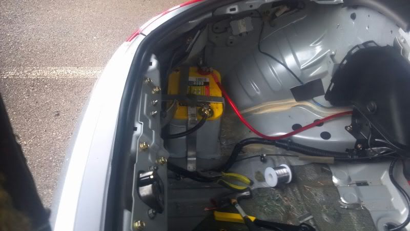
slight update, engine should be balanced as of last week just waiting on them to finish up the bore and hone, cleaning the block ect ect. since the car was running again and i fixed the problem which was the ipdm i continued on and pulled the old engine. slight change of plans since hobby shop is closed monday and sunday, i just said f it and am doing this in my driveway. definately hillbillyed the engine out using heavy duty tow straps across the 4x6 rafters, it only held a portion of the weight though me and a buddy where still doing a significant portion of the lifting. also cleaned up the wiring in the trunk a little for the fuel pumps and methanol pump, as well as sold the radio going to put the dual wideband controller there(i know not needed but well w/e), methanol controller, and turbo timer this will let me use some shorter wires on some stuff since ill use the old radio wiring for probably the turbo timer and haltech instead of uhhhhh well not sure what i wired it to currently. pulling the carpet out as well not going to have any in it since down the road i do plan on having at least a 6 point roll bar in it ill just have to cut it up anyway.
definately keeping the center console, door panels, dash ect in it. pretty much behind the driver seat and back the plastic is all going to be ditched though as well as the carpet just gets in the way trying to work on stuff anyway. never intended for this to be any type of show car though so not having a carpet wont bother me.
definately keeping the center console, door panels, dash ect in it. pretty much behind the driver seat and back the plastic is all going to be ditched though as well as the carpet just gets in the way trying to work on stuff anyway. never intended for this to be any type of show car though so not having a carpet wont bother me.
Last edited by jerryd87; Apr 14, 2012 at 08:12 PM.
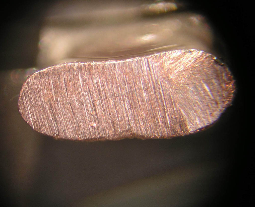
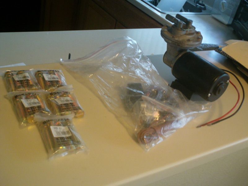
Couple updates got the vacuum pump in for the brakes, was running into some issues running out of vacuum after two presses of the brakes after boost just dint seem to be regenerating fast enough so this should solve that problem since i couldnt find a leak anywhere, even tryed pulling it out of gear to let it idle as well as leaving it in gear and coasting down. dint like it so this was the solution. recieved new lug studs to fit the 10.5 wheels front and back with spacers, just needed them for the front but they sent me a full set when i only ordered 10 so w/e ill use em all. some fittings from summit as well going to drill into the firewall and install the bulkheads to reroute the fuel lines, driveshaft tunnel gets kinda hot so i dont want the fuel lines running along the top of it so ill run them inside, as well as some T fittings to H the fuel lines togeather just in case i no str8 mentioned possible fuel pressure differences before since the lines where independant so i went ahead and did this just in case since im already rerouting stuff.
finally the old engine is partly apart, definately need to get new timing chains the main chain has a little too much slop and the driver side exhuast cam chain has WAY too much slop about 2 inchs of deflection on the side opposite the tensioner, mayby a little more. engine im being told will be done and ready to pick up next week so once i go get it ill put up plastic to create a clean room, as well as pick up prob a case of carb cleaner for parts, some more razor blades, gloves, lint free rags, and several boxs of seran wrap to wrap the engine when not working on it. probably take me two days or so to file fit the rings and make sure all clearances are set before i actually start assembly, but thats only a couple hours of working on it per day. block leave dosnt actually start until the 11th so im about a week ahead of schedule even with only a couple hours to work on it a day.
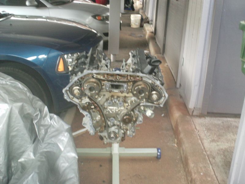
finally the old engine is partly apart, definately need to get new timing chains the main chain has a little too much slop and the driver side exhuast cam chain has WAY too much slop about 2 inchs of deflection on the side opposite the tensioner, mayby a little more. engine im being told will be done and ready to pick up next week so once i go get it ill put up plastic to create a clean room, as well as pick up prob a case of carb cleaner for parts, some more razor blades, gloves, lint free rags, and several boxs of seran wrap to wrap the engine when not working on it. probably take me two days or so to file fit the rings and make sure all clearances are set before i actually start assembly, but thats only a couple hours of working on it per day. block leave dosnt actually start until the 11th so im about a week ahead of schedule even with only a couple hours to work on it a day.
Last edited by jerryd87; Apr 21, 2012 at 08:46 PM.
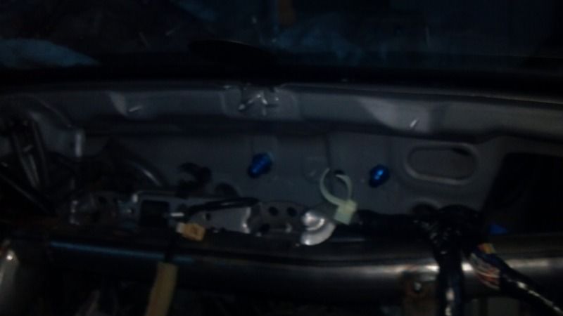
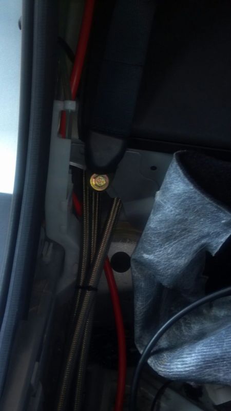
going kind of slow recently because im in the arms room late every day while we are doing reset. this is going to be the final resting place for fuel lines going into the engine bay. sorry for bad pics was getting dark out. going to clean up the hole in the front firewall a little still then use 1/2 inch vacuum line to make a grommet around the hole. inside i have rubber hose holders to route it to the edge of where the heater core/ ac box would be then down and along the right side of the car. still have to drill a hole in one of the floor braces for the lines and theres already a gap i can easily fit the lines through to where the fuel pump access plate is and back into the fuel swirl pot. also need to open the one hole up to put in the other -8an bulkhead. going to run without heat and ac for now since i dont use it anyway. ill keep the parts and put back in when i leave island if i go somewhere i need it. regulator is also going to mount right below where the vin number so i have room up front for oil catch can.

Last edited by jerryd87; Apr 24, 2012 at 09:18 PM.

Nice build man. Got to love the issues that come along with it all ha. But good luck with the rest of it and hope everything goes smoothly from now on. Anxious to see final results!

normally the kit is something like 280 bucks i got mine off ebay from a dude who sold his project big block chevelle before finishing it for 80 bucks. mine is a rebranded comp cams kit but its the same exact kit that ssbc sells, might be able to find something smaller for cheaper, this thing is made pretty beefy since some people rely on nothing but this for power assist.
Last edited by jerryd87; Apr 25, 2012 at 09:04 AM.
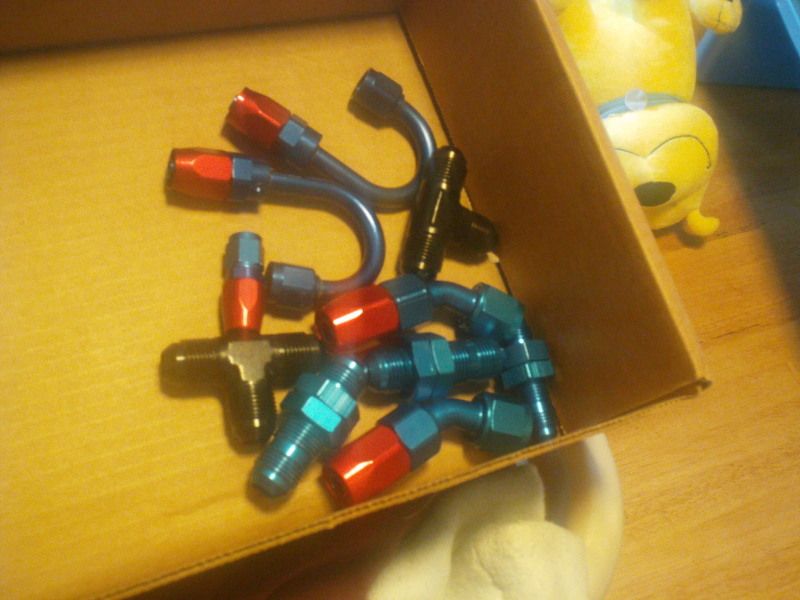
routed the new fuel lines and also used a t bulk head to build a line between the two feed lines since str8 mentioned it and............well just in case lol def gotta get two new -8an straights for the feed lines in the engine compartment though since im short two but other then that should be good once new engine goes in.
more pics tomarrow since somehow my phone AND camera are both dead right now. going to put some wrap on some wires then the interior will start going back in this weekend. engine is back from the machine shop and crank needed alot of work for balancing 4 different holes of various depths and then one hole had to be drilled and some mallory added. jwt flywheel needed a little worth for balancing as well. also been working on my center console its been fiberglassed so i can fit 4 extra guages in there as well the the greddy turbo timer. needless to say a radio and cubby no longer fit there which is fine with me ill have more pics of that tomarrow as well.
fuel lines
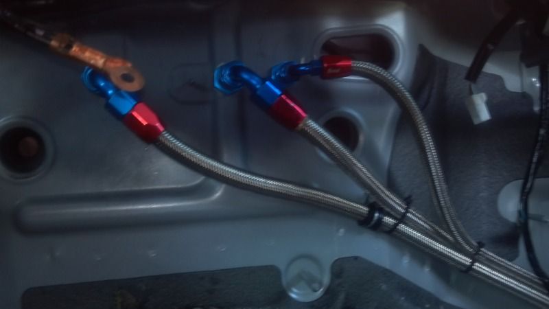
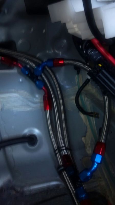
carpet def wont lay completely flat against this section but w/e
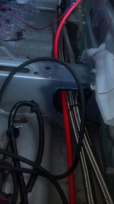
this is an attempt to keep them front getting kinked running over a bunch of crap
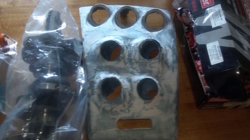
here is the new guage area need to final sand and prime it, can tell i used a different guage pod for the one. one is a auto meter dash mount pod the other three are butchered triple pillar pods. not perfect but the cars not going to be a show car so im not going to make molds and crap for a perfectly symmetrical setup. but i did mock them up so i can easily read them all from my peripheral from the driver seat.
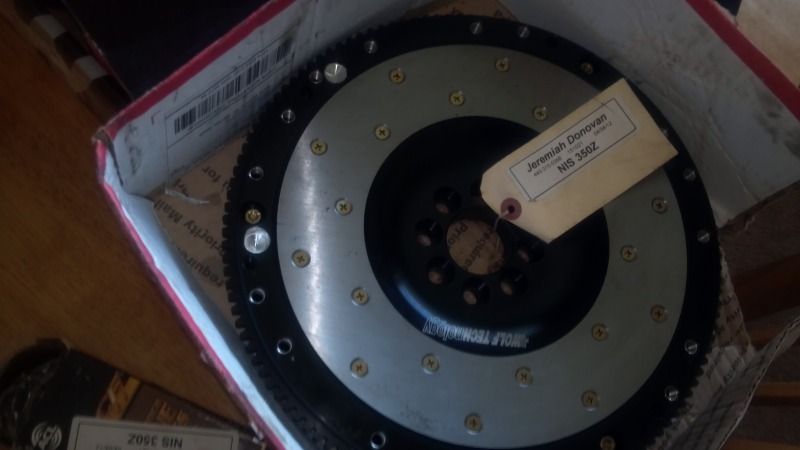
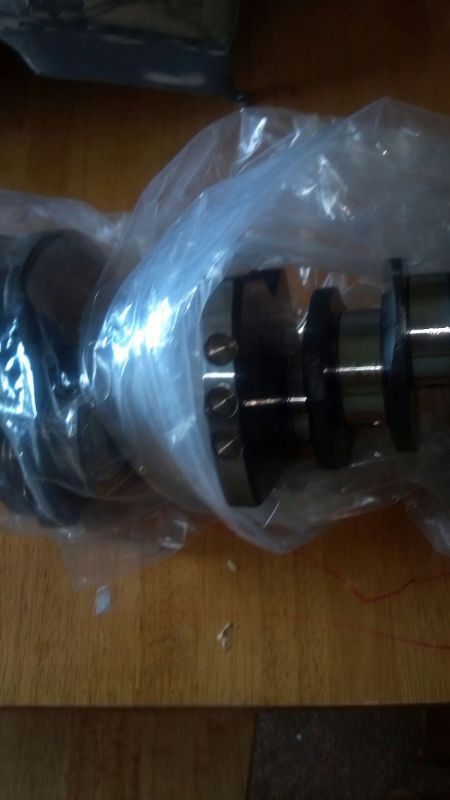
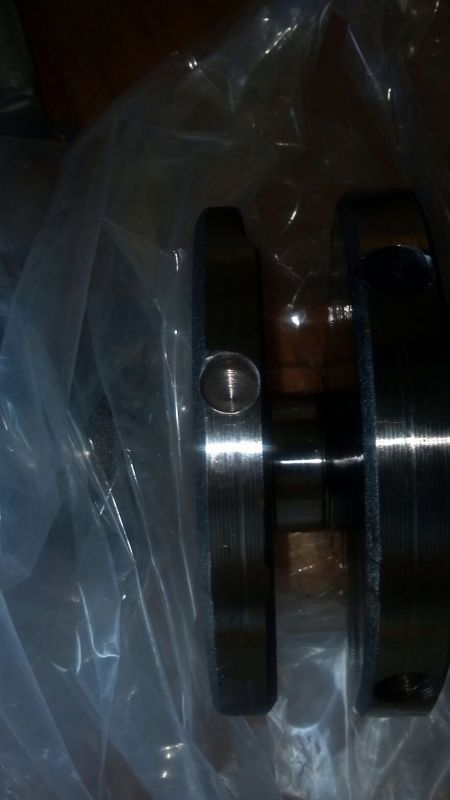
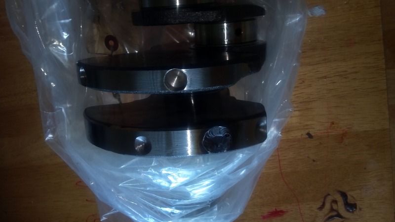
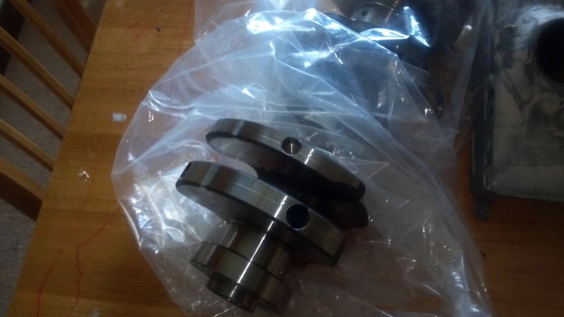
and all the crap balanced crank had alot more done to it then i initial saw, most of those holes are 1/4-1/2 inch deep, one on flywheel is about 3/8 deep and the other mayby 1/16th. can also see the mallory welded in. if anyone had any reservations about balancing there assembly this should put it to rest. this is balanced for wossner pistons and rings(about the same weight as cp), acl bearings, and pauter rods and as you can see the balance for the stock stuff is way off from where this stuff needs it to be.
more pics tomarrow since somehow my phone AND camera are both dead right now. going to put some wrap on some wires then the interior will start going back in this weekend. engine is back from the machine shop and crank needed alot of work for balancing 4 different holes of various depths and then one hole had to be drilled and some mallory added. jwt flywheel needed a little worth for balancing as well. also been working on my center console its been fiberglassed so i can fit 4 extra guages in there as well the the greddy turbo timer. needless to say a radio and cubby no longer fit there which is fine with me ill have more pics of that tomarrow as well.
fuel lines
carpet def wont lay completely flat against this section but w/e
this is an attempt to keep them front getting kinked running over a bunch of crap
here is the new guage area need to final sand and prime it, can tell i used a different guage pod for the one. one is a auto meter dash mount pod the other three are butchered triple pillar pods. not perfect but the cars not going to be a show car so im not going to make molds and crap for a perfectly symmetrical setup. but i did mock them up so i can easily read them all from my peripheral from the driver seat.
and all the crap balanced crank had alot more done to it then i initial saw, most of those holes are 1/4-1/2 inch deep, one on flywheel is about 3/8 deep and the other mayby 1/16th. can also see the mallory welded in. if anyone had any reservations about balancing there assembly this should put it to rest. this is balanced for wossner pistons and rings(about the same weight as cp), acl bearings, and pauter rods and as you can see the balance for the stock stuff is way off from where this stuff needs it to be.
Last edited by jerryd87; May 3, 2012 at 01:12 PM.

well now that it has been altered its -8 an feed into swirl pot, dual -8 an out to dual bosch 044, bosch 044 up to two -8an bulkheads in the firewall with a filter for each pump in these lines and the lines tied togeather with a short piece of -8an and -8an tee's under the carpet(when it goes back down.) then dual 8 an feed from other side of bulkhead into fuel rails. fuel rail return is dual -6 an 180 fittings from front rails to aeromotive fpr on the firewall and out from there into another bulkhead in the firewall. other side is -6an back into fuel swirl pot and th en a -4 an overflow from swirl pot to cjm fuel return correction kit in stock basket. basket also has a gss342 in it. down the road might ditch the haltech harness and pick up the plug in unit and use it to stage the fuel pumps and run a checkvalve on one of them. i wanna do it but not in a position to do so right now since it dosnt seem like ill ever get my per deim from deployment and the ****ing finance office is actually fighting me because they dont want to do work and want everyone to turn in there own ****.(half my brigade hasnt gotten it despite being back 2 months now.)