Injected Performance brings you HALTECH PLATINUM PNP STANDALONE

 06-30-2009, 04:15 PM
#562
My data logs are ending up corrupt.  When I hit view it tells me there was extra data in the frame or something and gives me the option of saving a binary dump. It calls it "fred.bin", attached. I was logging RPM, load, TPS, base fuel injection time, injector 1 injection time, O2 calibration Bank 2, O2 calibration Bank 1. I initially had a mix of 100ms and 5ms sampling, so I switched all of them to 100ms but both times got corrupt logs.
I will post over on the Haltech forum also Hal, but if you can confirm the problem and expedite resolution, that would be great.
Thanks.
EDIT: The Haltech forum doesn't allow attachments (zips anyway). I tried posting both my 70 kb and 200 kb dumps. The smaller one is allowed here at my350.
When I hit view it tells me there was extra data in the frame or something and gives me the option of saving a binary dump. It calls it "fred.bin", attached. I was logging RPM, load, TPS, base fuel injection time, injector 1 injection time, O2 calibration Bank 2, O2 calibration Bank 1. I initially had a mix of 100ms and 5ms sampling, so I switched all of them to 100ms but both times got corrupt logs. I will post over on the Haltech forum also Hal, but if you can confirm the problem and expedite resolution, that would be great.
Thanks.
EDIT: The Haltech forum doesn't allow attachments (zips anyway). I tried posting both my 70 kb and 200 kb dumps. The smaller one is allowed here at my350.
Last edited by rcdash; 06-30-2009 at 04:29 PM.
06-30-2009, 04:45 PM
#563
Registered User
iTrader: (11)

Join Date: May 2005
Location: New Jersey
Posts: 1,301
Likes: 0
Received 0 Likes
on
0 Posts
My data logs are ending up corrupt. When I hit view it tells me there was extra data in the frame or something and gives me the option of saving a binary dump. It calls it "fred.bin", attached. I was logging RPM, load, TPS, base fuel injection time, injector 1 injection time, O2 calibration Bank 2, O2 calibration Bank 1. I initially had a mix of 100ms and 5ms sampling, so I switched all of them to 100ms but both times got corrupt logs.
I will post over on the Haltech forum also Hal, but if you can confirm the problem and expedite resolution, that would be great.
Thanks.
EDIT: The Haltech forum doesn't allow attachments (zips anyway). I tried posting both my 70 kb and 200 kb dumps. The smaller one is allowed here at my350.
When I hit view it tells me there was extra data in the frame or something and gives me the option of saving a binary dump. It calls it "fred.bin", attached. I was logging RPM, load, TPS, base fuel injection time, injector 1 injection time, O2 calibration Bank 2, O2 calibration Bank 1. I initially had a mix of 100ms and 5ms sampling, so I switched all of them to 100ms but both times got corrupt logs. I will post over on the Haltech forum also Hal, but if you can confirm the problem and expedite resolution, that would be great.
Thanks.
EDIT: The Haltech forum doesn't allow attachments (zips anyway). I tried posting both my 70 kb and 200 kb dumps. The smaller one is allowed here at my350.
Did you try to delete your old datalog and try starting fresh?
That worked for me
07-01-2009, 05:36 AM
#565
rcdash, which software/firmware are you on now? Not sure what would be causing the corruption, but as a fix I would suggest you delete all the logged channels except 1 (required), change your trigger, disable logger, save the map, power down the ecu and ecu manager software. Then open ecu manager, power up ecu, change your trigger, add your channels, power cycle the ecu, and save your map.
Side note: you can now log 20 channels (increase from old 10 channel limit)
Side note: you can now log 20 channels (increase from old 10 channel limit)
07-01-2009, 05:38 AM
#566
rcdash, which software/firmware are you on now? Not sure what would be causing the corruption, but as a fix I would suggest you delete all the logged channels except 1 (required), change your trigger, disable logger, save the map, power down the ecu and ecu manager software. Then open ecu manager, power up ecu, change your trigger, add your channels, power cycle the ecu, and save your map.
Side note: you can now log 20 channels (increase from old 10 channel limit)
Side note: you can now log 20 channels (increase from old 10 channel limit)
I have ECU manager 1.04, firmware 1.04, data log viewer 1.00 (not beta)

 07-01-2009, 08:54 AM
#570
Having spare compensation maps that can be triggered by an external trigger (such as a line for METHANOL ON or METHANOL FAILURE) is something available in the Sports series and it is my understanding that development is aligning feature sets into the future. Looks like this new fuel map is the first step in that direction.
 I didn't have to go through the series of steps to change parameters - just disabled log, erased log, re-enabled, rebooted ECU and was good to go.
My data log viewer says 1.1.0.0 by the way. But that was what was bundled from your website.

Last edited by rcdash; 07-01-2009 at 08:56 AM.
 07-02-2009, 07:08 PM
#572
Hi Hal,
This new 1.04 package is pretty neat. It lets you play with the Sports series maps as well. Do you have a version that lets you edit advanced parameters like the transient throttle delta load dead band for the 350z maps?
I already tried to fool it by changing the extension of the 350z map to a hs2-104 but it's smart and knows it's a 350z map and hides certain menus and screens.
EDIT: Hal, sent you an e-mail today with some logs and also posted a pic on Haltech's user support forum related to transient throttle.
Last edited by rcdash; 07-03-2009 at 08:44 AM.
07-16-2009, 06:45 AM
#573

Is there a wiring diagram somewhere on how to setup the 2 step? I dont want to buy a KP module if the Haltech already does this 
Thanks Hal for confirming that for me.
I have it set to the quick disconnect.
I'm not running a Relay.
I have no issue taking off the clutch pedal assembly again and replacing the switch if this is the way it is going to be from now on.
Also going to the new FW there would be no need to retune?
Car got tuned Saturday on Dyno but it will be awhile before we road tune
the way I'm figuring is that I should be k. Correct me if I'm wrong.
Glad to see you got home safe
07-16-2009, 09:53 AM
#574
http://www.injectedperformance.com/h...fo.htm#twostep
Lots of good info here: http://www.injectedperformance.com/haltech/
Lots of good info here: http://www.injectedperformance.com/haltech/
Last edited by rcdash; 07-16-2009 at 09:54 AM.
07-17-2009, 05:32 AM
#575
sweet.
It says supplied connectors, so I assume those 2 and 3 wire breakouts come with the haltech?
i'll have my haltech on tuesday, but it will sit until everything gets swapped.
Hopefully the unit fits behind my custom kickpanels.
It says supplied connectors, so I assume those 2 and 3 wire breakouts come with the haltech?
i'll have my haltech on tuesday, but it will sit until everything gets swapped.
Hopefully the unit fits behind my custom kickpanels.
Last edited by str8dum1; 07-17-2009 at 06:02 AM.
07-17-2009, 06:04 AM
#576
rcdash, thanks for providing the links.
str8dum1, Yes, the mating two, three and four pin connectors come with the Haltech. I just updated the two step wiring information with regards to when it is active. Please review again, as Haltech reversed the activation permanently starting with firmware version 1.04.
http://www.injectedperformance.com/h...fo.htm#twostep
07-17-2009, 06:17 AM
#577
Edit-- i see a pic on injectedperformance where it has all the break out wires. the attached pic must be an older wiring harness.....
So for the 2step, you are basically just joining those 2 wires to a switch on the breakout to activate? Are there any relay diagrams on how you are incorporating those 2 trigger wires into the clutch switch?
Also, i guess you either use the AIT in the MAF or the external sensor, correct? I bought the external sensor so I can properly read AIT's after my meth nozzle.
Finally, does the Haltech shift light http://www.injectedperformance.com/e....aspx?ID=10388 work with the 350z PnP? Didnt see wiring diagram for that, so I guess not?
Last edited by str8dum1; 07-17-2009 at 08:08 AM.
07-18-2009, 06:21 AM
#578
I recall someone posted a DIY (but the wiring is now reversed as Hal mentioned).
You can use the AIT on the MAF sensor and in fact you will want to wire in your aftermarket AIT sensor (should you decide to use it) right into the MAF wiring so that the stock ECU still gets temp readings.
Not sure about the shift light (though the outgoing programmable aux line is there and could be used).
Last edited by rcdash; 07-18-2009 at 06:22 AM.
07-18-2009, 08:39 AM
#579
Registered User
iTrader: (11)
Join Date: May 2005
Location: New Jersey
Posts: 1,301
Likes: 0
Received 0 Likes
on
0 Posts
I recall someone posted a DIY (but the wiring is now reversed as Hal mentioned).
You can use the AIT on the MAF sensor and in fact you will want to wire in your aftermarket AIT sensor (should you decide to use it) right into the MAF wiring so that the stock ECU still gets temp readings.
Not sure about the shift light (though the outgoing programmable aux line is there and could be used).
You can use the AIT on the MAF sensor and in fact you will want to wire in your aftermarket AIT sensor (should you decide to use it) right into the MAF wiring so that the stock ECU still gets temp readings.
Not sure about the shift light (though the outgoing programmable aux line is there and could be used).
Let the OEM MAF Harness alone so the OEM ECU is reading from the MAF and HAltech is reading from the IAT
As far as the wiring for the 2 step it's still the same you just need a N.O switch now instead of a N.C switch
https://my350z.com/forum/forced-indu...h-control.html
KevinAPEX did a DIY for the 2 step in that thread but most pics don't work.
If you need the pictures I might have them and I will rehost them
07-18-2009, 08:57 AM
#580
Registered User
iTrader: (11)
Join Date: May 2005
Location: New Jersey
Posts: 1,301
Likes: 0
Received 0 Likes
on
0 Posts
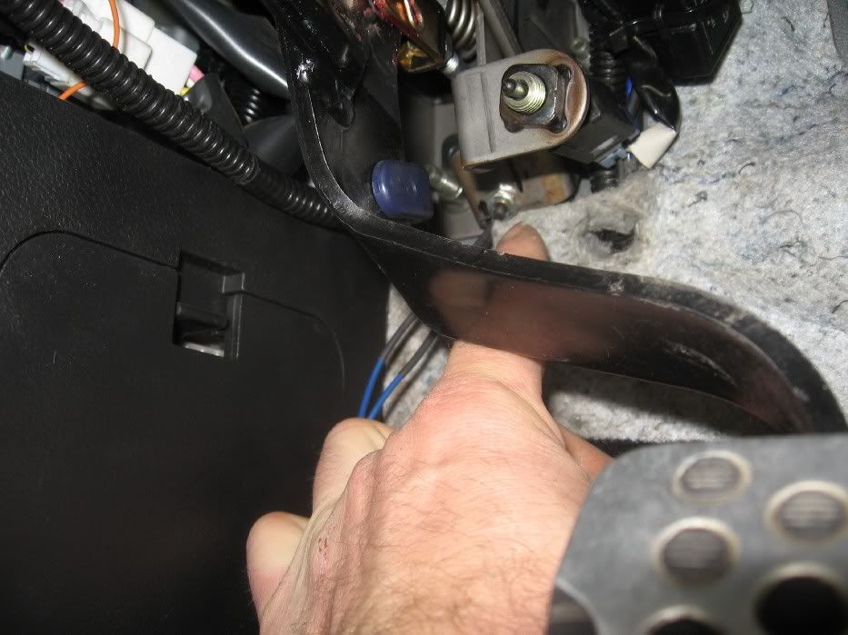
It's all done, I added a normaly open micro switch at the bottom travel of the clutch, so when the clutch is all the way to the floor the Haltech will only let it rev. to pre-set, 2k, 3k, 8k, whatever you choose. Once you let off the clutch motor revs to redline.
I also added a over-ride toggle switch so when the switch is off, system works like above described, when toggle is set to the on position, regardless of clutch position motor will rev to redline.
Thanks Hal for the help, Haltech master!
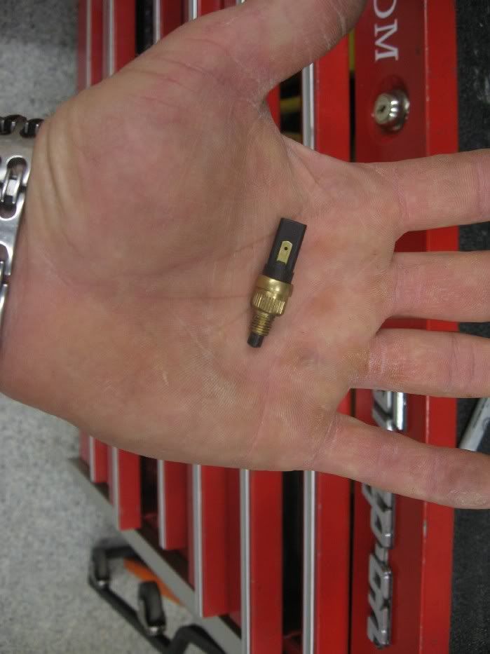
Switch for the clutch- switch normally open.
Solder leads to switch/ ground one side to frame
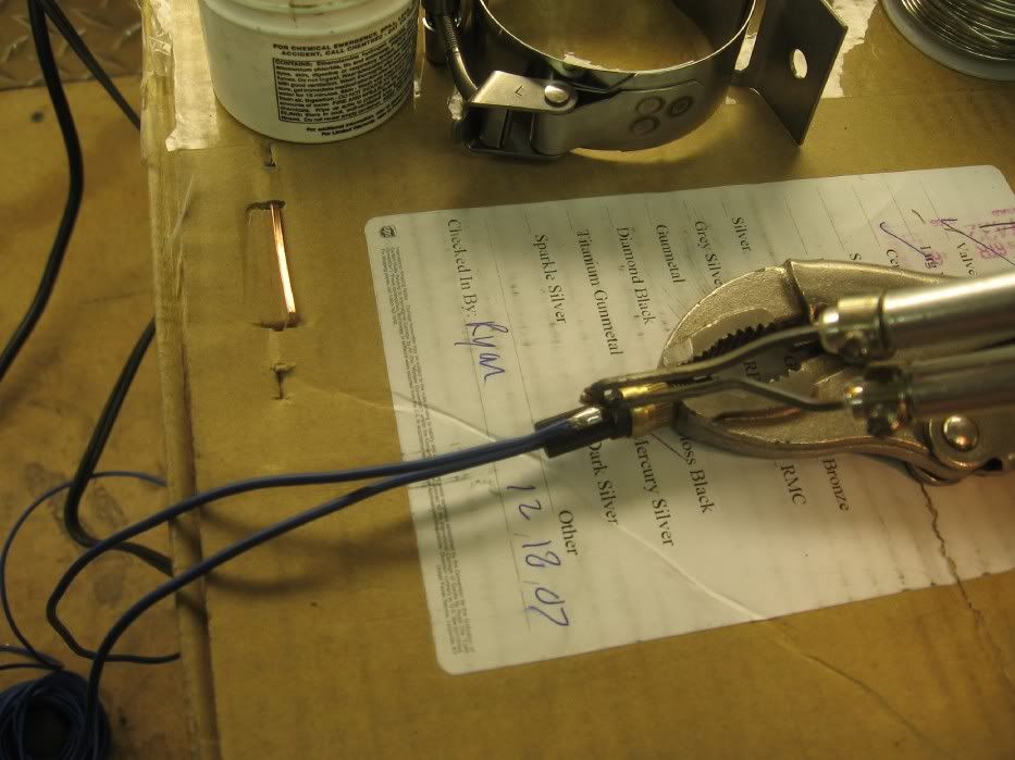
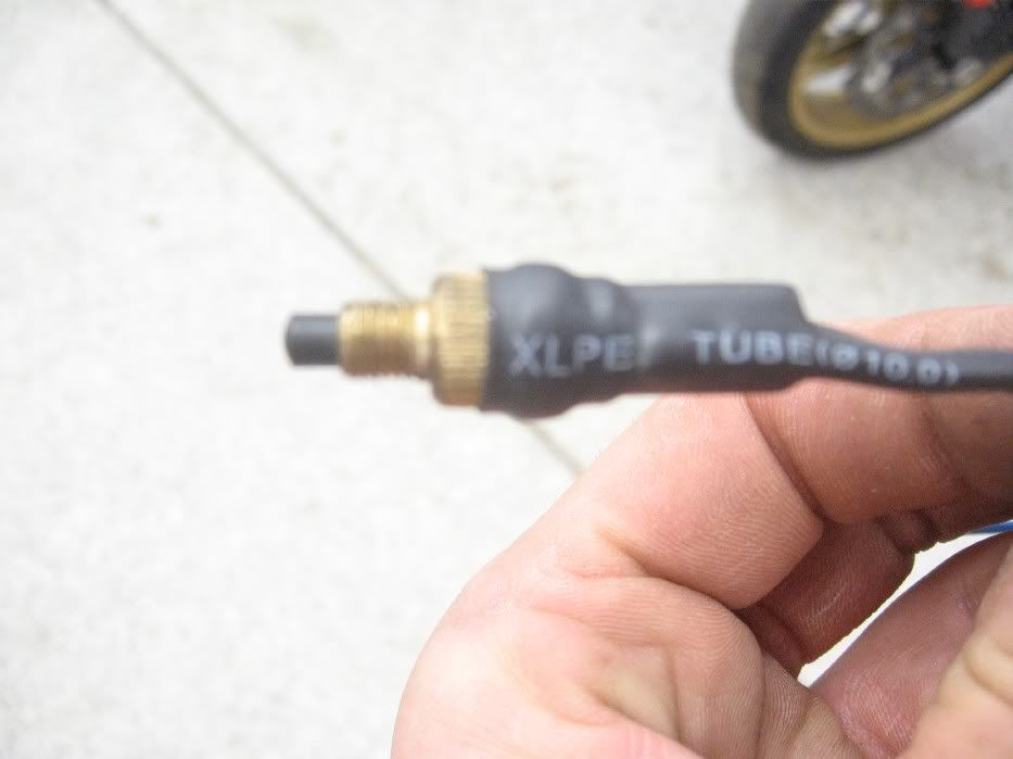
Shrink wrap leads on switch
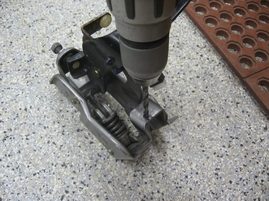
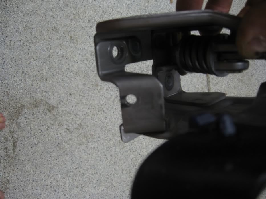
Clutch assembly
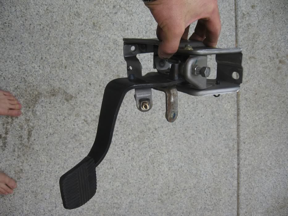
Drill hole in stop to locate switch
Switch location, clutch assembly back in car
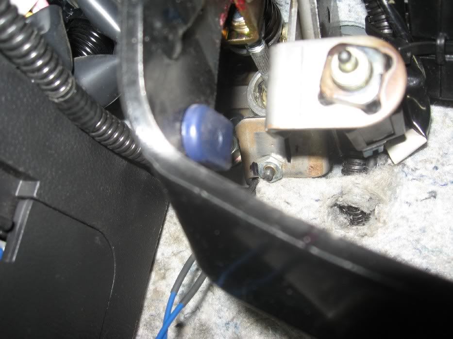
Over-ride togg. switch location

Done
I also added a over-ride toggle switch so when the switch is off, system works like above described, when toggle is set to the on position, regardless of clutch position motor will rev to redline.
Thanks Hal for the help, Haltech master!
Switch for the clutch- switch normally open.
Solder leads to switch/ ground one side to frame
Shrink wrap leads on switch
Clutch assembly
Drill hole in stop to locate switch
Switch location, clutch assembly back in car
Over-ride togg. switch location
Done
Spelled checked
Images Rehosted
Changed to current working switch
Last edited by Glex25; 07-18-2009 at 08:58 AM.