When you click on links to various merchants on this site and make a purchase, this can result in this site earning a commission. Affiliate programs and affiliations include, but are not limited to, the eBay Partner Network.
I hate USPS! They made an 8 hour drive take 48 hours. As of 1pm my intake was 5 hours away. It's supposed to be here by 8pm tonight. I should have ridden a bycicle to go get my new intake.....FCK YOU USPS!
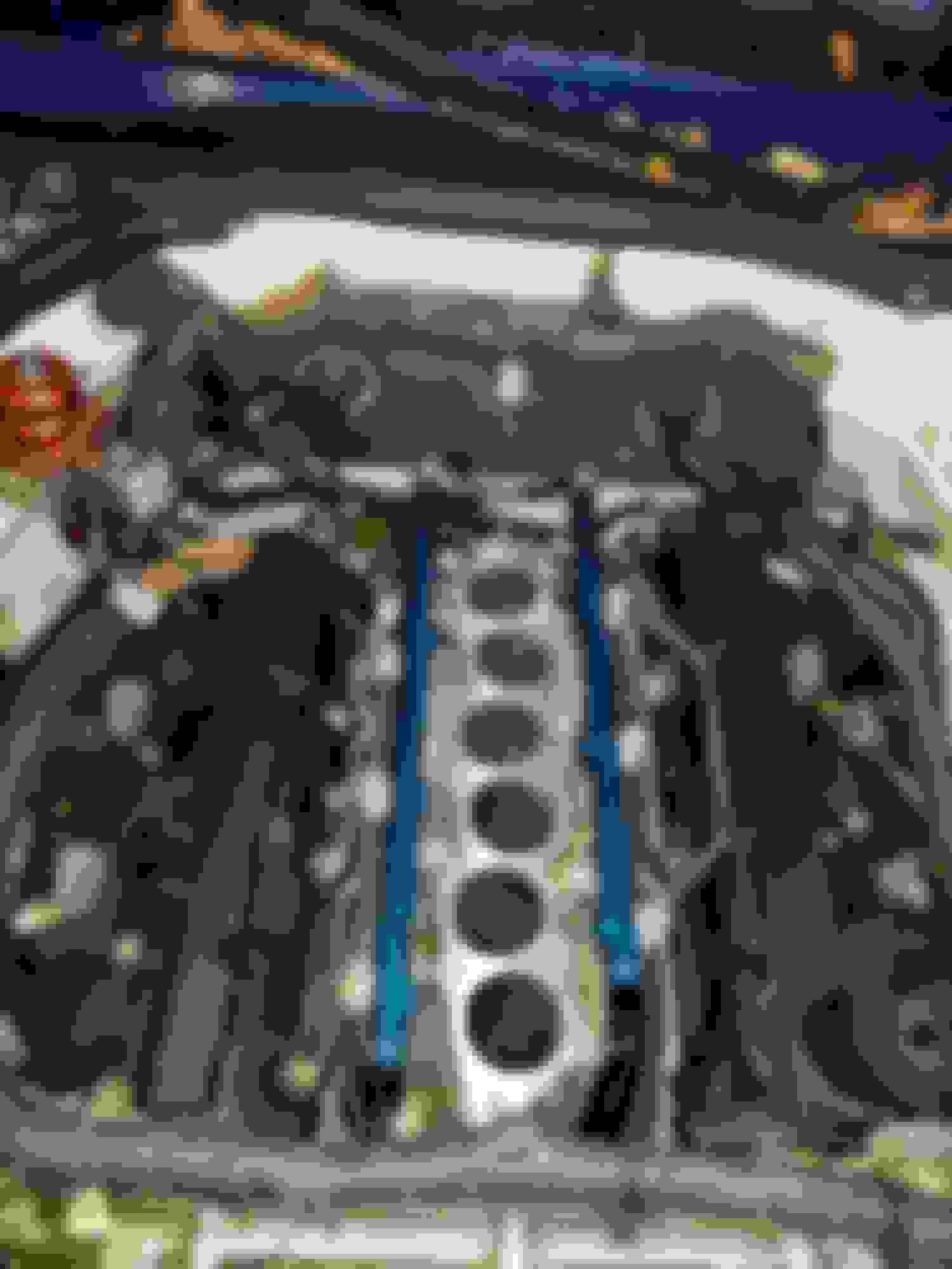
Ok well i finally got my Intake today....The suspense sucked!!!
Here are some pictures.
Temp installed while i figure out some fuel line issues.
Weight of OEM manifold with 5/16 spacer. 25.1 Lbs
New Kinetix Manifold 12.6 lbs. So its a solid 12 lbs of the front of the nose. Not much but it all adds up.
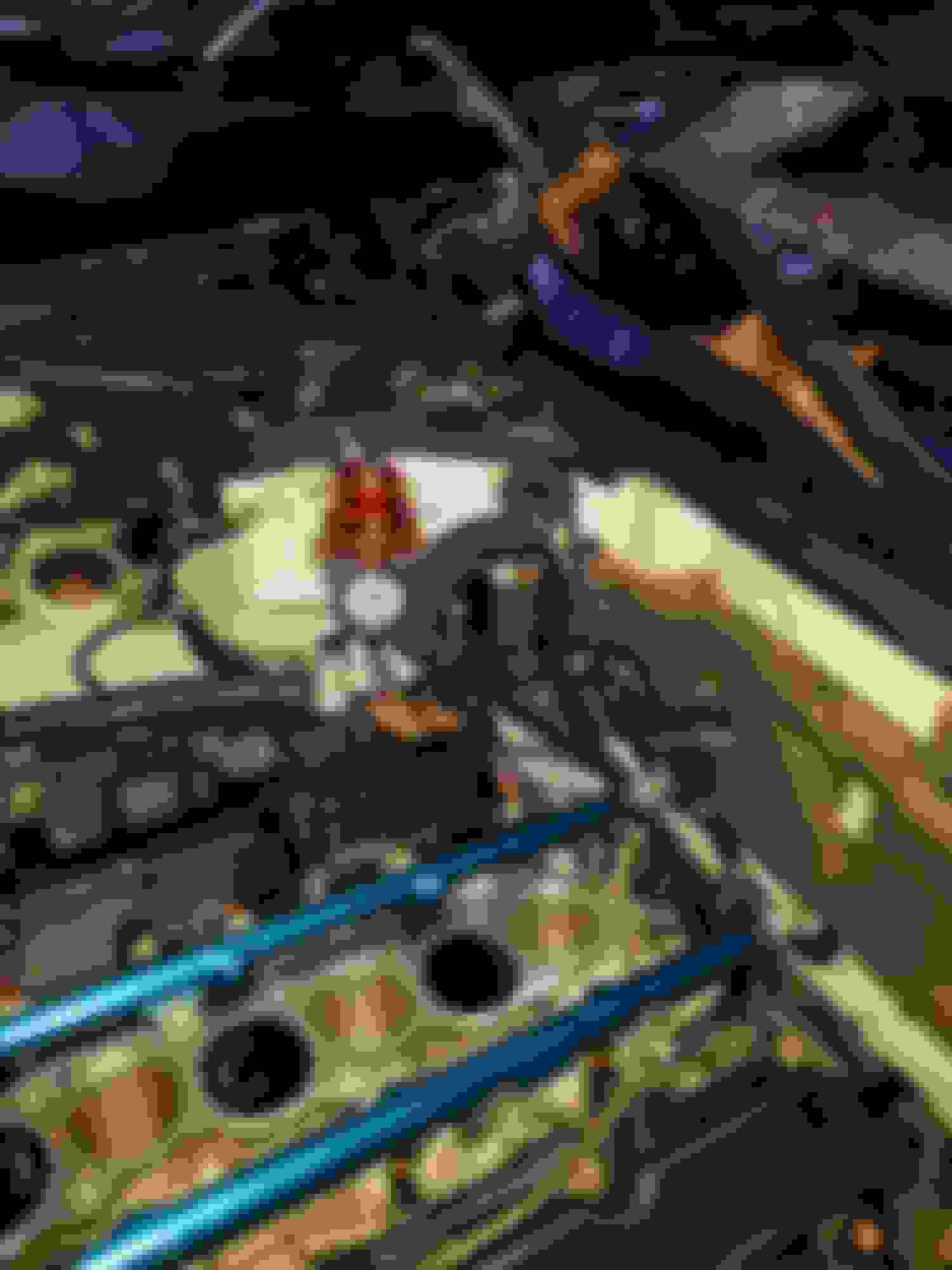
Ok so here is my new problem, when i tried to install new intake it was hitting my fuel pressure regulator so i had to move it a foot to the left (passenger side) so it would clear. The problem now is that my current fuel lines aren't long enough to work so i need some new ones.
While i'm in there i'm wanting to clean it up a little bit and go from a dual input/ dual out to a single in single out, but i need some professional help. I'm thinking it shouldn't effect the amount of fuel flowing since the FPR is keeping it at a steady fuel pressure but i want to make sure before i order some fuel lines.
Sorry for the crappy pain picture but i hope it make sense.
Last edited by Conway_160; Oct 22, 2018 at 05:03 PM.
a 13lb intake is pretty sweet - especially off the front of the car...
no no no ... dont do 'new' ... you're inherently starving and offer a pressure differential between injectors. The last cylinder on your diagram (call it cylinder 6) is going to run lean.
Dont reinvent the wheel ... yes, you got hoses everywhere but there a reason it's designed this way.
Ordered my new fuel lines, the should arrive Friday. Hopefully only take a few hours to get everything squared away then we'll see if i can tell a difference with the butt dyno.
Got a surprise in the mail today, i recieved my fuel lines and fittings. Even though amazon said they are still trying to fill the order. So tomorrow ill hook everything up and check for leaks and make my grand voyage.
Got a surprise in the mail today, i recieved my fuel lines and fittings. Even though amazon said they are still trying to fill the order. So tomorrow ill hook everything up and check for leaks and make my grand voyage.
What exactly are you doing? Are you setting up a return fuel system? what sized lines are you going after?
What exactly are you doing? Are you setting up a return fuel system? what sized lines are you going after?
Since the neck of the kinetix is so close to the fire wall i had to move my FPR to the passenger side a good bit. It used to set just below the stamped vin on the false firewall, now it sets on the battery compartment false fire wall. The problem then became that fuel return line from the passenger side rail was no longer long enough to reach the FPR. So i just bought 6' of new fuel line with -6 fittings to make longer lines. Ill post some pictures when i get home tonight.
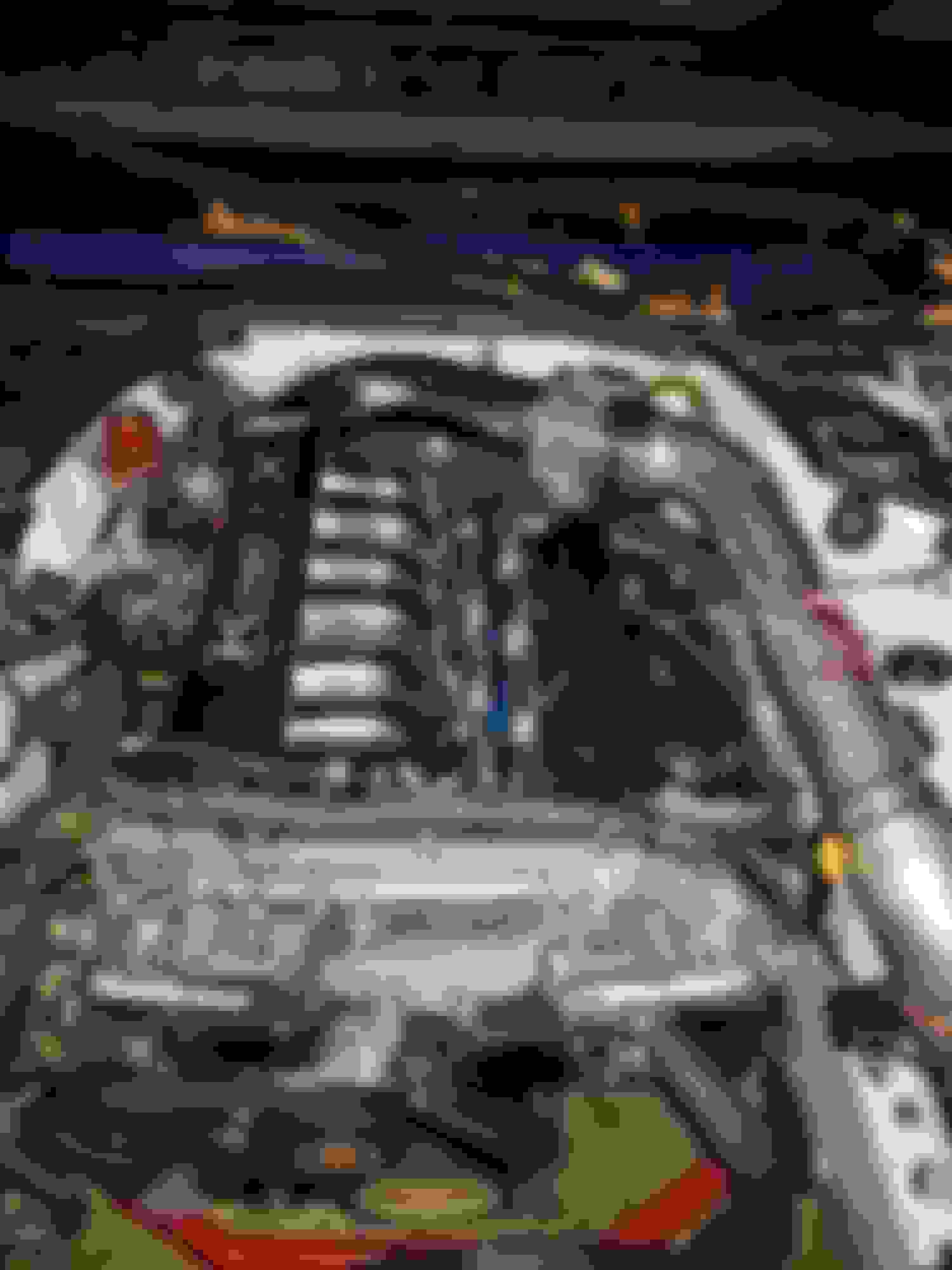
So this is the new fuel lines installed and all tucked away, no leaks so that's good. If you look you can see the two holes in the back where the FPR used to sit. Over view of fuel lines
Some day ill do a wire tuck, and this will look way cleaner. New FPR Location
As you can see this looks so much cleaner than the stock manifold. Installed ready to go
Some things to note:
1. It does feel like i lost some power but only a dyno can verify. But i may be able to gain that power back with tune adjustment.
2. It makes a odd sound. You can hear the air rushing through the intake at idle, it has a hiss to it. I don't think there is a vacuum leak but i will double check that later.
3. My boost gauge is more steady when i'm accelerating (odd right).
4. The sound of the car is noticeably different under WOT, its hard to explain. With the old intake when i got in higher RPM i could hear the pitch of the exhaust hit a higher ricer note. Now with this intake it keeps a deeper sound and i can hear way more noise from the engine bay.
To recap, i need a tune and it makes the engine bay cleaner.
looks good ... get that dyno scheduled!!! I'll be interested to see how the numbers fall.
Wire tuck for sure - it'll show off the other work you've got going on in there.
Thoughts on chopping off the mounting tab on your intake tube?
Im going to make sure the EVAP sensor doesnt need to be mounted in a particualr way. Right now its just kind of hanging there. But i would like to cut it off to gain more room and clean it up.
That 90* bend on the intake pipe @ the air filter is a power killer.
Mine isn't a 90* i would say at max a 60* but i get what your saying. I want it to be as straight as possible for as much velocity as possible. I would think it being a 3" tapering down to a 2.5" would act like a velocity stack to help mitigate the curve.
That 90* bend on the intake pipe @ the air filter is a power killer.
Conway - this isnt anything against you...you know I only want the best for ya! AND, I will eat-crow if the manifold puts down more power with or without a modification to your tune!!
but its such a poor design...all show and no go...
It's worse than a 90* ... it's closer to 135* ... and it's right after a ~30* and then you have another ~90* to get into the runners and then a gradual ~70* to get into the manifold.
And although the runners are equal length, they are un-equal length from the 3" feed source and the rough edges within the airbox discourage laminar airflow.
And further more your passenger side air flow is making a U-turn (of sorts) as it dives into the cylinder while your driver side cylinders are making an S-turn.
Do the runners taper down in length? and is there any sort of velocity stack on the end of each runner?
ehhhh...not a fan of these and especially at $700 a unit - insult to injury!!
The 90* bend I referred to and which Conway said is actually a 60* is not at the manifold. It's the intake pipe at the filter.
The Kinetix Velocity is actually a great manifold. It was the SSV that gave this manifold a bad name but the Velocity is much improved and beneficial on a naturally aspirated engine. The newest record holder for an n.a. Z, can't remember his name, said the Velocity added 4-5 mph to his 1/4 mile time and he tested many different intakes and combo's.
The best intake setup for a naturally aspirated Z would be to get the throttle body relocated and facing the battery box, relocate the battery and use the battery box to house the air filter. Run a 4" or even a 5" intake pipe from a large bore throttle body to the new "air box".
The best setup for FI would be to delete the intercooler and rely solely on water inject both pre and post compressor.
Both scenarios avoid as much pressure loss as possible and would make things as efficient as they could possibly be. Ultimately, a 4 or 5" upper plenum neck matched to the same sized throttle body matched to the same sized intake pipe with as few bends and to the smallest degree possible would yield the best results imo.
Here's a link to my diy "build thread". There's a lot of info on here, ton's actually. Below is a copy of some of my research that's on my thread regarding intake pipe sizing. https://www.infinitiscene.com/thread...230572/page-11
Easy Performance CAI System Design Consideration Primer
" What this means is going from a 4 inch duct to a 3 inch ID duct increases the friction losses by ~2.7 times. Thus, it is not hard to see that a 4 inch duct is preferable over a 3 inch duct by reducing friction losses as well as lowering the air velocity by nearly half. "
" If a 90� bend is designed into the intake duct, then the following can be estimated as shown in the following table. In these examples, 3" and 4 " ID pipes are given. For these pipe sizes, the centerline radius of close 90� elbows are typically equivalent to the diameter of the pipe.
These calculations illustrate the addition of a single 90� bend in a 3-inch or 4-inch duct is the same as adding 48 inches or 64 inches of straight duct respectively in its place. When compared to the rather short length desired for the intake duct, adding a single bend has a dramatic affect on increasing the intake's resistance to airflow. For bends other than 90�, they can be estimated by multiplying the 90� bend resistance by a percentage factor. For a 45� bend, the total friction loss is about 65% of the 90� bend's resistance. For a 180� bend, the total friction loss is about 140% of the 90� bend's resistance.
From the above table, one might conclude that the 48 inch equivalent length given by a 3 inch ID pipe would provide less friction than the 64 inch equivalent length for a 4 inch ID pipe. However, one must now determine the friction that is produced by these two pipe sizes before making such a judgment. As shown earlier, the 3 inch pipe has 2.69 times more friction than a 4 inch pipe. If you calculate the equivalent length of 4 inch ID pipe that would have the same friction as the 90� bend in a 3 inch ID pipe, then you would need to multiply the 48 inch equivalent length by 2.69. This result tells us the 90� bend in a 3 inch pipe is equivalent to 119 inches of 4 inch ID straight pipe. Thus, having bends and smaller pipe diameter is detrimental towards producing good flow characteristics in an induction system."
" Materials that have high reflectivity coefficients are primarily metals and of those, copper, silver, gold and aluminum are among the highest. All of these metals have reflectivity coefficients above 0.96. This means they reflect more than 96% of all the thermal radiation that strikes their surface. For the construction of induction systems, aluminum tends to be a good material of choice. Plastics and other organic materials tend to be very poor at reflecting radiant heat. The reflectivity coefficients of plastics and rubbers tend to be below 0.06. This means plastics only reflect less than 6% of all the thermal radiation that strikes their surface. This means over 94% of the radiant heat is absorbed by the plastics or rubbers. Consequently, they are undesirable materials when exposed to radiant heat. "
" Summation
When considering how to design an optimal induction system for a particular vehicle, all of the design aspects discussed earlier as well as other characteristics must be given careful consideration. Restricting the design considerations to the aspects discussed above, some basic design conclusions can be listed.
Select a high flow surface impingement style filter element
Use as large a filter element as practical for the application
Position the filter so the least amount of dirt and debris will be entering the filter
Maintenance the filter regularly to maintain optimal performance
Use as large of an intake duct as practical to connect the filter element to the engine
Intake duct's interior surface should be as smooth as possible
Avoid rapid changes in diameters/cross-sectional areas through the induction system
Avoid or limit the bends needed in the induction system
Keep the intake track to the engine as short as possible
The induction system should draw 100% of its air from outside the engine bay or where minimally higher than ambient air temperature regions exist
All induction component surfaces that are exposed to higher temperature components and surfaces should be made of highly thermal reflective materials
All surfaces that come in contact with the intake air should be insulated from all potential heat sources "
Last edited by onevq35de; Nov 2, 2018 at 03:55 PM.